



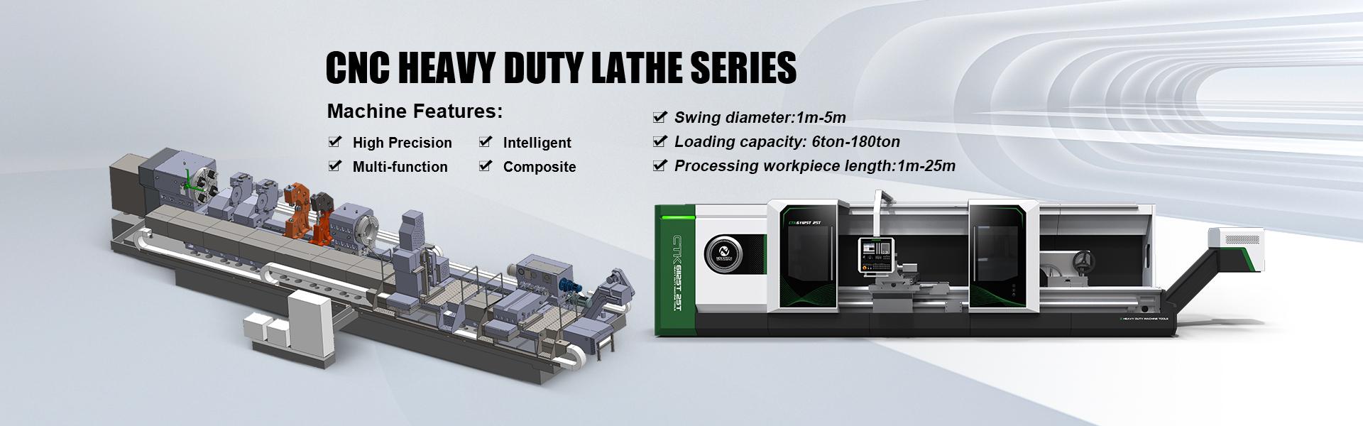
Product Features:
1. Machine model and name
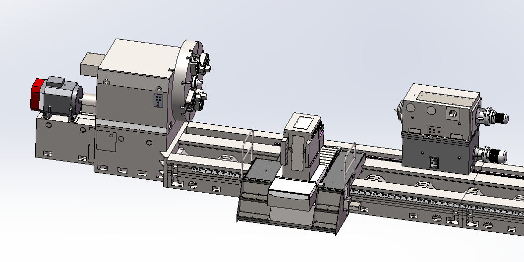
CK61XXX series CNC Heavy duty horizontal lathe for 30tons,40tons and 50tons without sliding cover
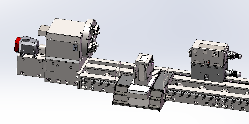
This machine tool is primarily designed for machining various rotary parts, such as external cylinders, end faces, grooves, tapers, arcs, curved surfaces, and threads.
As a CNC heavy-duty horizontal lathe developed by our company, it features the following characteristics:
- A separated main drive and feed drive system;
- Equipped with a Siemens 828D CNC system;
- Full closed-loop control achieved through linear scales on the X-axis and Z-axis;
- A monolithic bed with triple guideways;
- A through-shaft design for the main spindle head supported at both ends, with a maximum speed of 160 r/min;
- Standard box-type tool post (optional vertical 4-station electric turret);
- Powered movement for both the tailstock and tailstock sleeve;
- Tailstock locking and sleeve clamping employing either a disc spring clamping with hydraulic release mechanism or manual locking;
- Configured with an operator platform and pendant button station for convenient operation.
Environmental Temperature: 5℃–45℃
Relative Humidity: ≤85%
Power Supply System: 3-phase 380V±10%
Power Frequency: 50Hz±2Hz
4、Main Parameter
Swing diameter over machine bed | mm | 1600~3500 |
Turning Diameter Over Carriage | mm | 1250~3000 |
Max. workpiece length between centers | mm | 5000~20000 |
Max. workpiece weight between centers | t | 32、40、50 |
Bed guideway configuration | Monolithic Bed with Triple Box Guideways |
Spindle speed range | r/min | 0.8-160 |
Number of spindle speed steps | RPM | Two-speed mechanical gearbox with stepless speed regulation within each range |
Spindle nose type | 1:30 L-type taper 1:30 | |
Center size and angle | Short taper | 1:4 φ100mm、 φ125 mm、φ140 mm |
Spindle drive motor | kW | AC 90、110 (spindle servo motor) |
Maximum spindle torque | kNm | 68、84 |
Chuck jaw type | mm | 4-jaw independent chuck |
Upper tool post type | Box-type (main + aux plates) | |
Tool shank cross-section | mm | 70×70 |
Max. cutting force at tool post | kN | 70 |
Longitudinal/Cross feed gradation | Stepless | |
Longitudinal/Cross feed range | mm/min | 0.1-1000 |
Rapid traverse (X/Z) | mm/min | 4000 |
Z-axis drive motor | Nm | 50 |
X -axis drive motor | Nm | 30 |
Least input increment Z/X | mm | 0.001 |
Tailstock sleeve diameter | mm | 320、400、460 |
Tailstock sleeve travel distance | mm | 300 |
Tailstock center(Built-in live center) | Short taper | 1:4 φ100mm、 φ125 mm、φ140 mm |
Tailstock sleeve movement type | Powered | |
Tailstock movement type | Powered | |
Sleeve travel speed | mm | 50 |
Tailstock rapid traverse speed | mm/min | 2000 |
Tailstock sleeve clamping | Disk spring clamping / Hydraulic release |
Supporting range (open-side steady) | mm | User-specified |
Supporting range (enclosed steady) | mm | User-specified |
Spindle radial runout (at flange face) ≤0.015mm
Within 500 mm from spindle nose ≤0.040mm
Spindle axial play ≤ 0.015mm
Radial runout of spindle center ≤0.020mm
Radial runout of tailstock center ≤0.020mm
Working Accuracy
Roundness ≤0.012mm
Cylindricity ≤0.04/500mm
Flatness of finish-turned plane ≤0.025/300mm measuring length
Surface roughness (standard test piece): External cylinder Ra1.6
aper & curved surface Ra3.2
6、Structural Description of Main Components:
This machine tool primarily consists of the following parts:Bed,Headstock,Headstock base,Main motor and motor base,Chuck,Enclosed steady rest,Open-side steady rest,Tailstock,Tool post,Operator platform,Hydraulic system,Electrical system,CNC system,Standard accessories.
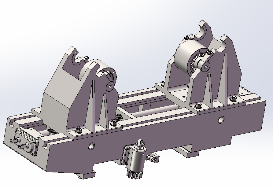
6.1machine bed
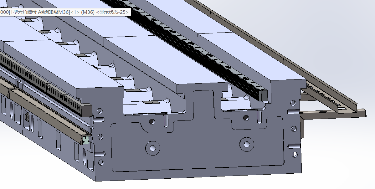
The machine bed of this machine tool is made of high-strength cast iron material using resin sand molding. The bed body features an integral three-rail design, providing excellent anti-overturning performance when supporting the workpiece. The main guide rails of the bed undergo medium-frequency quenching treatment, achieving a hardness of no less than HRC 50 (with a process soft zone intentionally left in the middle of the rails during quenching), significantly enhancing the wear resistance of the bed.
The bed is the foundational component of the machine tool, and its rigidity directly affects the overall working performance and machining accuracy of the entire machine. The bed of this machine tool is cast using resin sand molding and high-quality cast iron, ensuring excellent appearance and strength. Its structure incorporates a rational rib layout, providing superior resistance to sectional deformation. This design increases the overall damping of the bed, effectively improving the machine tool's vibration resistance. Chip discharge holes are located at the bottom of the machine, ensuring good chip removal capability. Wear-resistant material is applied to the sliding surfaces of the bed saddle, reducing friction and extending the machine tool's service life.
To further minimize the impact of cutting overturning moments on the machine tool and ensure operational precision, the entire length of the bed is supported on multiple adjustable pads and secured by ground screws. This configuration increases the contact area between the bed and the foundation, enhancing the long-term stability of the machine bed's precision.
6.2Headstock
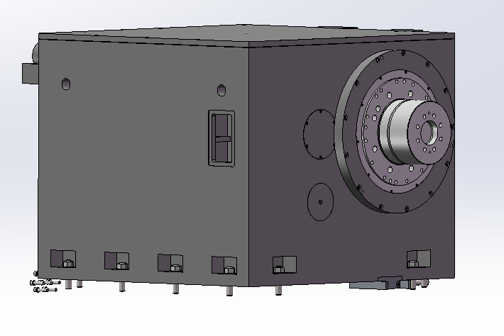
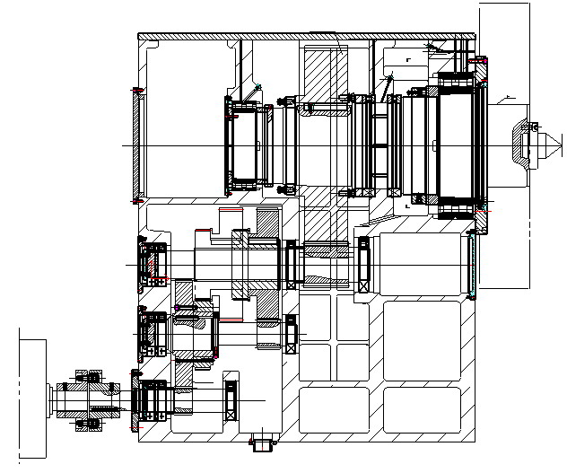
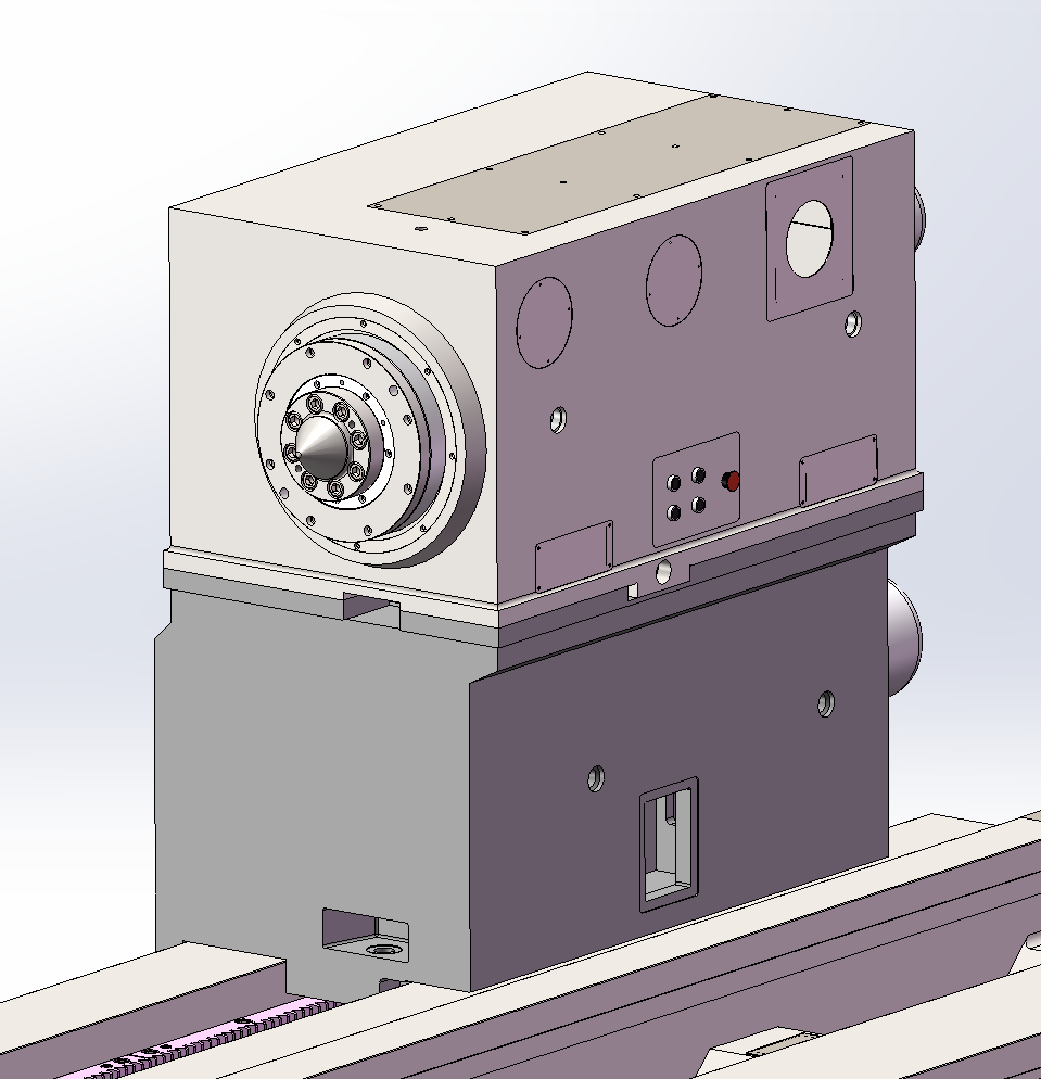
The headstock features an independent hydraulic control system and lubrication system. The headstock is bolted to the base, which is in turn bolted to the bed. The machine spindle utilizes reputable brand bearings, ensuring high spindle rigidity and rotational accuracy. The spindle center adopts a flange-mounted short taper shank design, positioned via conical surface and secured to the spindle with screws, enhancing connection rigidity between the center and spindle.
The main drive employs an AC spindle servo motor with B3-type mounting. It incorporates a two-stage mechanical speed change mechanism with a 1:4 ratio per stage, achieving an overall speed range ratio of 1:200. This provides the spindle with a speed range of 0.8-160 r/min. The two-stage mechanical speed change in the headstock is actuated by an electromagnetic slide valve and hydraulic cylinder. Both front and rear sides of the headstock are equipped with button stations for controlling spindle forward/reverse jogging, continuous operation, and stopping.
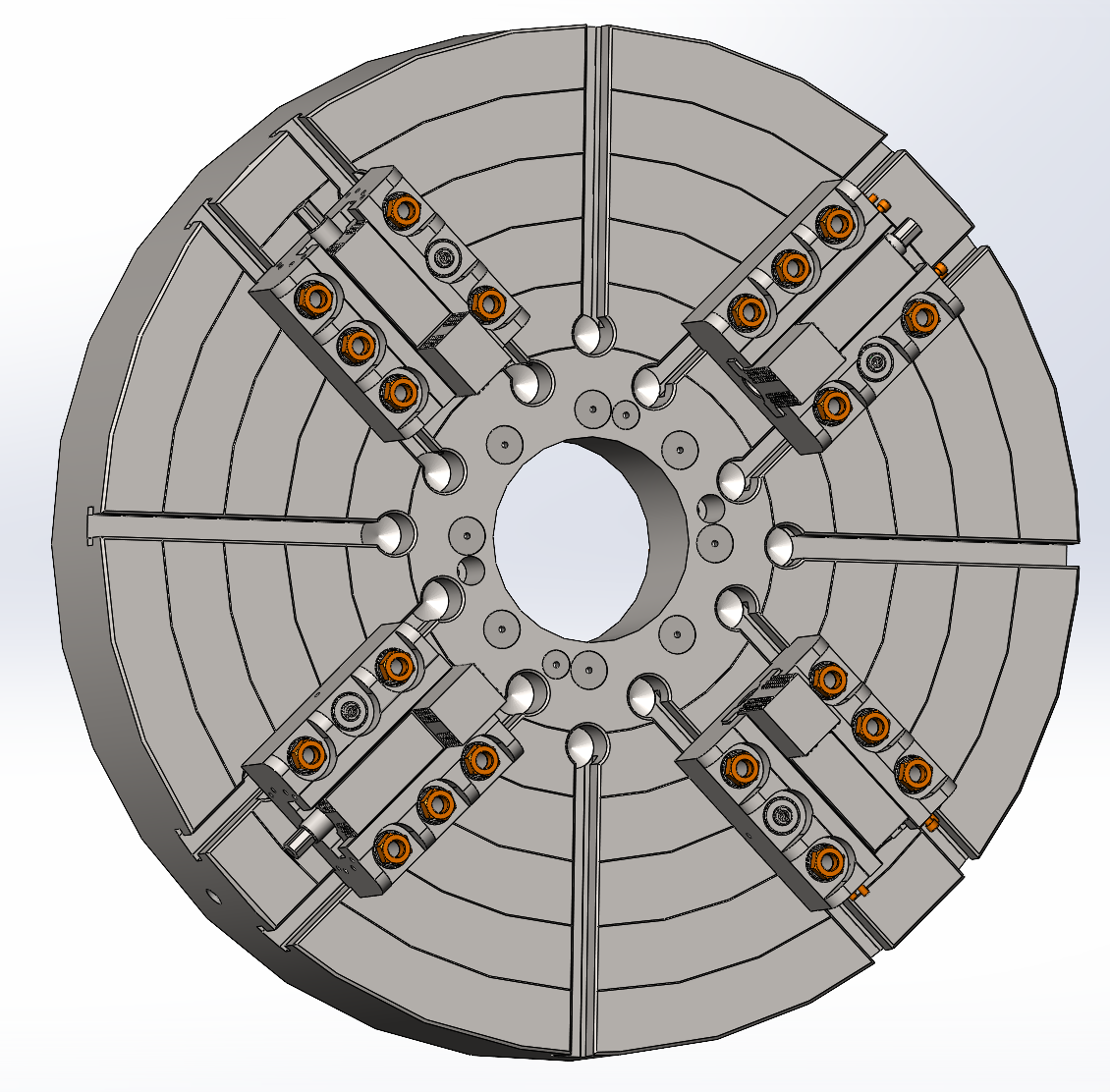
The chuck is made of ZG310-570 cast steel. It connects to the spindle through a 1:30 taper interference fit, integrating with the spindle as a single unit to ensure reliable anti-deformation capability and connection rigidity.
For workpiece clamping, this machine employs a heavy-duty chuck with mechanical jaws. Using a specialized wrench and two gear segments on the jaw bodies, it achieves force-amplifying workpiece clamping, significantly reducing operator labor intensity and improving efficiency. A flow sensor is installed in the recess on the back of the headstock to trigger alarms when lubrication volume is insufficient. An encoder is added at the rear of the spindle to enable thread cutting.
6.3Tailstock
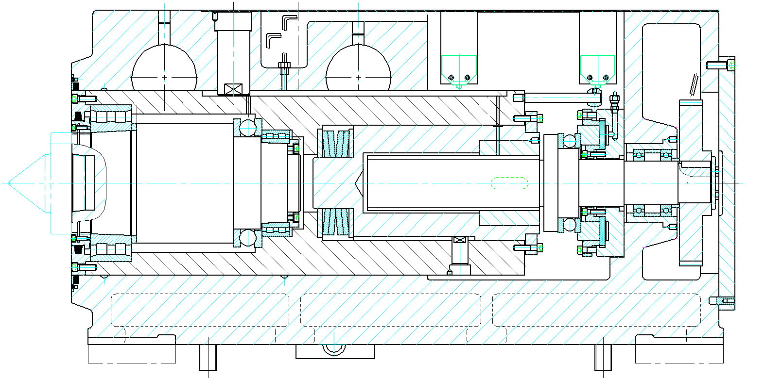
The tailstock adopts a two-piece split design (upper and lower bodies). The lower body contains the tailstock rapid traverse mechanism, tailstock clamping mechanism, lubrication unit, hydraulic unit, etc. Within the upper body of the tailstock, the front end of the tailstock quill spindle is supported on a double-row radial roller bearing, providing rigidity equivalent to the main spindle structure. The rear end of the tailstock spindle is equipped with a Belleville spring that prevents mechanism damage caused by workpiece thermal expansion, ensuring the center spindle remains unaffected by workpiece deformation during machining. It incorporates a power-operated quill movement mechanism, quill locking/release mechanism, and hydraulic force-measuring device. The center employs a flange-mounted short taper shank design. Pressure gauges are installed on both the front and rear faces of the tailstock, allowing operators to select and set the appropriate pressure indicator position based on workpiece weight according to the thrust force calibration plate.
The external surface of the tailstock features calculation plates indicating thrust forces for different center angles and workpiece tonnage ranges.
The tailstock and tailstock quill each have dedicated motors for rapid movement, with integrated overload protection. Tailstock traverse utilizes a gear-and-rack transmission system, ensuring smooth and reliable motion. After positioning, manual locking is achieved via a locking plate and pressure plate. Wear-resistant material is bonded to the sliding surfaces to effectively reduce wear on the bed guideways.
Tailstock movement incorporates overload protection and is equipped with reliable positive stops.
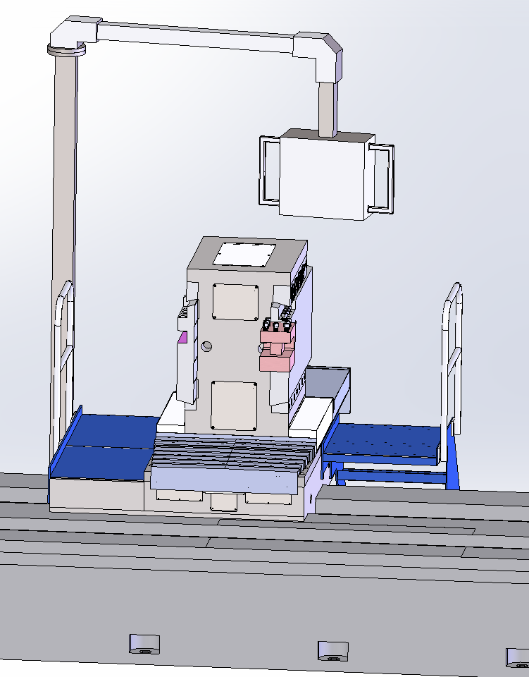
The Frame-Type Tool Post is designed for heavy-duty horizontal lathes, used for roughing and finishing various shaft-type workpieces. It is particularly suitable for heavy cutting (rough machining), step shafts, deep grooves, and face machining. The tool holder plates are divided into main and auxiliary plates, mounted on both sides of the tool post body. They can extend/retract independently and are secured to the tool post body via pressure plates. The extension length is manually adjustable, and plate movement is manually operated.
The tool post integrates the longitudinal carriage and upper tool post into a single unit. Longitudinal movement employs a dual-gear-and-rack backlash elimination structure, ensuring high transmission rigidity. The feed box and longitudinal carriage form one integrated assembly. A servo motor drives a reducer to transmit motion to gears and racks, moving the carriage. This guarantees transmission accuracy while enhancing load capacity.
Both Z-axis and X-axis movements are driven by AC servo motors. Rapid traverse rates:
Transverse (X): 4000 mm/min
Longitudinal (Z): 4000 mm/min
Feed rate ranges:Transverse: 0.1–1000 mm/min
Longitudinal: 1–1000 mm/min
The upper section of the tool post body adopts a frame structure with vertical left/right tool plates, offering greater rigidity than conventional designs for heavy cutting. Main/auxiliary plate movement is manual; positions are locked manually after adjustment for flexible operation and secure clamping.
X-axis and Z-axis guideways are lubricated by a centralized lubrication system with configurable oil volume and timing.
Operator platforms with handrails are installed on both sides of the tool post, featuring upper/lower steps. The control panel rotates and moves for ergonomic operation.
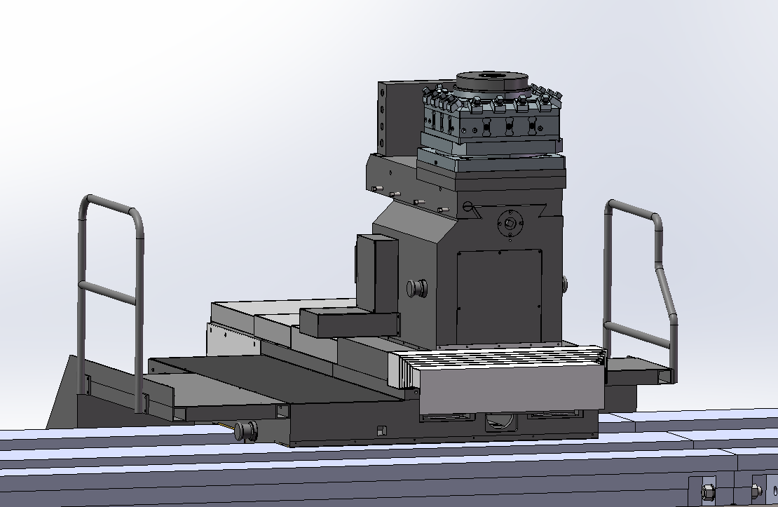
Electric Vertical Four-Station Tool Turret (optional)
It can automatically change tools upon receiving a tool change command from the CNC system. Suitable for continuous machining of multiple processes on workpieces, offering convenient tool changing, time savings, and improved efficiency.
The tool turret consists of a large carriage, an upper tool holder, and a lower tool holder. The transverse movement of the upper tool holder employs a ball screw transmission structure, driven by a servo motor that transmits motion to the ball screw via a reducer. The movement of the lower tool holder is manually adjusted, allowing the operator to tailor it to workpiece requirements. The longitudinal movement of the large carriage adopts a dual gear-rack backlash elimination structure to transmit motion to the carriage, ensuring smooth operation, high transmission rigidity, and guaranteeing transmission precision and load capacity.
Both the Z-axis and X-axis of the tool turret are driven entirely by AC servo motors. The transverse rapid traverse speed is 4000 mm/min, with a feed range of 0.1–1000 mm/min. The longitudinal rapid traverse speed is 4000 mm/min, with a feed range of 0.1–1000 mm/min.
An operator walkway is installed on the tool turret. The main pendant control station is mounted on the walkway for convenient operation.
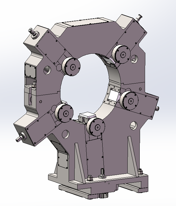
6.5Center Rests
This machine tool is equipped with one set of closed-type center rest and one set of open-type center rest. The closed-type center rest adopts a roller-slider mechanism; the open-type center rest features a wheel-type structure. Center rests use manual gear-rack adjustment for positioning only. All center rests can be manually moved longitudinally along the machine bed.
All parts of the machine tool are equipped with independent lubrication systems.
The hydraulic system is divided into two major parts: the headstock hydraulic system and the tailstock hydraulic system.
The main function of the headstock hydraulic system is to lubricate the bearings and gears inside the headstock, and to operate the headstock gear shifting cylinder.
The main function of the tailstock hydraulic system is the loosening/clamping of the tailstock sleeve.
The kinematic pairs of the tool turret are lubricated by a centralized lubrication station.
A work lamp is mounted on the top of the tool turret.
The machine tool is equipped with a tool cooling system, which effectively reduces the temperature in the cutting zone during turning operations, prolongs tool life, and improves machining accuracy.
The machine tool is equipped with a chain-plate-type automatic chip conveyor that automatically collects chips into a chip collection tank.
7、Machine Tool Electrical Configuration
The spindle servo motor and drive adopt a domestic system, while the CNC system employs the Siemens 828D system.
The electrical control cabinet features an aesthetically pleasing design, with gaps specially sealed for dust prevention.
All internal electrical components are selected from reputable brand products.
The cabinet is equipped with an air conditioner.
This electrical control cabinet delivers excellent stability and reliability.
No. | Name | Quantity | Purpose/Function | Manufacturer | Note |
1 | Precision Spindle Bearings | 1set | Headstock | NSK | |
2 | Precision Tailstock Bearings | 1set | Tailstock | NSK | |
3 | Other Bearings | 1set | Domestic Premium Brands | ||
4 | Ball Screw | 1set | X-axis | Domestic Premium Brands | |
5 | Precision Rack | 1set | Z-axis | Taiwan YYC | |
6 | CNC System | 1set | Tool post | Siemens 828D | |
7 | AC Servo Motor | 2sets | X-axis,Z-axis | Siemens | |
8 | Feed Drive System | 2sets | X-axis,Z-axis | Siemens | |
9 | Spindle Motor Drive | 1set | Supersync or MK | ||
10 | AC Spindle Servo Motor | 1set | Supersync or MK | ||
11 | Electrical Control Cabinet | 1set | Domestic Premium Brands | ||
12 | Control Cabinet Air Conditioner | 1set | Domestic Premium Brands | ||
13 | Major Electrical Components | 1set | Suzhou Siemens/Schneider | ||
14 | Major Hydraulic Components | 1set | Domestic Premium Brands | ||
15 | Linear Encoder | 1set | X-axis, Z-axis | Fagor | |
16 | X-Axis Precision Planetary Gear Reducer | 1set | X-axis | Nuosida or Equivalent |
No | Name | Quantity | Note |
1 | machine bed | 1set | |
2 | Headstock | 1set | |
3 | Chuck | 1set | |
4 | Headstock base | 1set | |
5 | Tailstock | 1set | |
6 | Feeding box | 1set | |
7 | Tool post | 1set | |
8 | Motor base | 1set | |
9 | Cable Carrier | 1set | |
10 | Foundation Mounting Kit | 1set | |
11 | Accompanying Tools | 1set | |
12 | CNC control system | 1set | |
13 | Hydraulic system | 1set | |
14 | Open-Type Center Rest | 1set | |
15 | Closed-Type Center Rest | 1set | |
16 | Operator Walkway | 1set | |
17 | Spare Parts | 1set | |
18 | ool Cooling System | 1set | |
19 | Automatic Chip Conveyor | 1set |
No | name | Part Number/Standard Part | Specification | Quantity | Purpose | Note |
1 | Chuck Torque-Multiplying Wrench | 1 | Chuck | |||
2 | Headstock Center | 75° | 1 | Spindle | ||
3 | Tailstock Center | 75° | 1 | Tailstock Shaft | ||
4 | Lifting Lug | CK61160G-01210 | 60-M60 | 4 | Headstock | |
5 | Lifting Lug | CK61160G-01211 | 55-M42 | 8 | Tailstock, Tailstock Lower Body | |
6 | Double-Ended Wrench | S91-1 | 22X24 | 1 | ||
41X46 | 1 | |||||
7 | Single-Ended Wrench | S91-2A | S=18 | 1 | ||
S=24 | 1 | |||||
S=36 | 1 | |||||
S=55 | 1 | |||||
8 | Square-Head Screw Wrench | S92-5 | S=30 | 1 | 50 screw | |
9 | Hex Key / Allen Wrench | S91-7 | S=4 | 1 | ||
S=5 | 1 | |||||
S=6 | 1 | |||||
S=8 | 1 | |||||
S=10 | 1 | |||||
S=17 | 1 | |||||
S=19 | 1 | |||||
S=22 | 1 | |||||
10 | Grease Gun for Disassembly | SYB-2 | 1 | Chuck,Spindle Bearing | ||
11 | Wooden-Handle Screwdriver | 12‘’ | 1 | |||
12 | Cutter Clamping Screw Wrench | 1 |
Product Parameters:

Whatsapp Code


 +86-151 6596 4868
 +86-151 6596 4868
 +86-151 6596 4868
 susan@novatechlathe.com
