



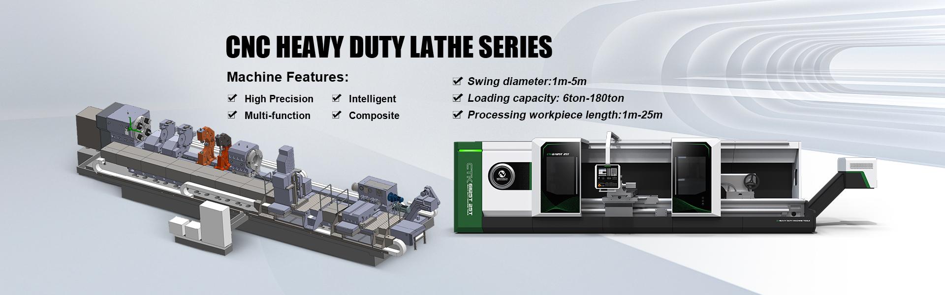
Product Features:
Product Design Structure Description
1.1 Working Conditions of the Product
1.1.1 Power Supply: Three-phase 380VAC ± 10%, 50HZ ± 1HZ.
1.1.2 Environmental Temperature: -5°C to 40°C
1.1.3 Relative Humidity: Average relative humidity 85%, maximum relative humidity 100%
1.2 Product Features:
This machine tool is a dedicated machine for processing wind turbine shafts. It consists of a headstock, a headstock base, an integral three-guide rail bed, a tool holder, a tailstock, an electrical control system, and a lubrication system. The main drive and feed drive are separated, and it has a numerical control function. The head of the machine is installed on the base of the headstock, the tool holder is installed on the carriage of the integral three-guide rail bed, and the tailstock is installed on the tailstock guide rail of the integral three-guide rail. The main shaft drive motor is installed on a separate motor base. This machine tool is suitable for turning the inner and outer circles, inner and outer conical surfaces, special surfaces, and turning end faces and threads of large shafts, discs, and cylindrical parts using high-speed steel and hard alloy cutting tools.
1.3 Main technical parameters
Project | Units | Parameter | |
Parameter | The maximum turning diameter of the bed body | mm | Φ4000 |
The maximum turning diameter for machining | mm | Φ3500 | |
The width of the bed body | mm | 2800 | |
The maximum length of the workpiece | mm | 6000 | |
The maximum load-bearing capacity between the two centers | T | 50 | |
The maximum torque of the chuck | kN.m | 70 | |
The maximum main cutting force | kN | 50 | |
principal axis | Diameter of the front support bearing of the spindle | mm | Φ460 |
Conicality of the inner hole of the spindle | 1:4, Φ125 | ||
Top angle | Degree | 75/60 | |
Form of the spindle head | 1:30 Long Cone | ||
Range of spindle speed | r/min | 1-160 | |
Power of the main motor | kW | AC90 | |
Diameter of the spindle chuck | mm | Φ3000 four-jaw single-action | |
Support type tool holder | X-axis travel of the tool holder and tool plate | mm | 500 |
X-axis travel of the tool holder | mm | 1200 | |
Z-axis travel of the tool holder | mm | 6000 | |
Tool cross-sectional dimensions | mm | 70×70 | |
Tailstock | Sleeve diameter | mm | Φ400 |
Maximum stroke of the sleeve | mm | 300 | |
Sleeve moving speed | mm/min | 50 | |
Spindle taper hole | mm | Metric 125 1:4 | |
Top angle | Degree | 75/60 | |
Tailstock moving speed | mm/min | 2000 | |
Tailstock longitudinal travel | mm | 5000 | |
Weight and appearance | Overall dimensions (length × width × height) | mm | 11000×4500×3200 |
Total weight of the machine tool | kg | Approximately 95,00 | |
Total power of the machine tool | kVA | 140 | |
Accuracy | Radial runout of the main shaft and tail shaft taper holes | mm | 0.02 (close to the main shaft end) |
Axial movement of the main shaft and tail shaft | mm | 0.02 | |
Top movement | mm | 0.025 | |
Roundness of the precision-turned standard specimen | mm | 0.02 | |
Cylindricity of the precision-turned standard specimen | mm | 0.025/300 | |
Flatness of the precision-turned standard specimen | mm | 0.02 (300 measurement diameter) | |
Processing accuracy | IT6 | ||
Surface roughness Ra value | μm | 1.6 (Standard Specimen) | |
Machine tool noise | DB(A) | 85 | |
Repeatability positioning accuracy of feed axis (X/Z) | mm | X∶0.01 Z∶0.035 | |
Positioning accuracy of feed axis (X/Z) | mm | X∶0.02 Z∶0.05 | |
1.4 Description of the main components' structure of the machine tool
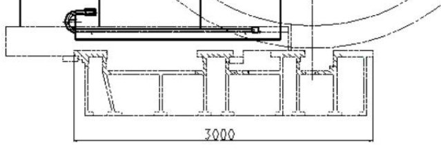
1.4.1 Bed: The bed of this machine tool is made of high-strength cast iron material HT300 and is shaped using resin sand casting technology. The surface of the guide rails undergoes medium-frequency quenching, with a hardness of up to HRC50. The sliding surface of the bed saddle is coated with wear-resistant material, which not only reduces friction but also extends the service life of the machine tool.
The bed of this machine tool adopts an integral four-guide rail structure, with a bed width of 3000mm. The bed is fixed on the foundation, which enhances the maintainability of the bed's accuracy. The surface of the bed is medium-frequency quenched, achieving a hardness of HRC50.
The integral three-guide rail beds of the machine tool are all fixed on shims, to improve rigidity and accuracy. The shims are fixed on the foundation.
1.4.2 Headstock:
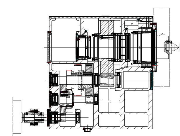
The spindle box is a closed box structure. The spindle is of a modular type with a high-stiffness short spindle structure. It is supported on high-precision cylindrical roller bearings. There is a large torque transmission gear in the middle of the spindle, which has good dynamic balance characteristics. The spindle system has high rigidity and high transmission efficiency.
The spindle box is equipped with an independent hydraulic control system and lubrication system. The spindle box is fixed to the spindle box base, and the spindle box base is integrated with the bed. The spindle top is a φ125mm flange-type short taper shank top. The spindle bearings are selected from domestic renowned brands. The spindle diameter is 460mm, with strong rigidity and high rotational accuracy.
The main drive adopts an AC servo motor for the spindle, with a power of 90KW and an installation type of B3. This enables the spindle to achieve a speed range of 1 - 160 r/min. The secondary mechanical speed change of the spindle is realized by an electromagnetic solenoid valve - hydraulic cylinder. On both the front and rear sides of the spindle box, there is a button station, which can realize the forward and reverse point operation, stop, emergency stop, and control of the main spindle's long travel.
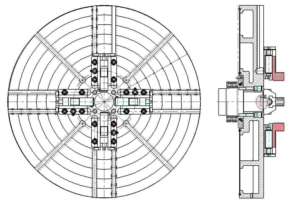
The tool holder is tightly fixed on the spindle by screws and an interference fit conical surface. It has four ordinary jaws, enabling positive and reverse positioning as well as positive and reverse clamping. The spindle head end is a flange-type short conical shank head, which is tightly fixed on the front end of the spindle by screws and an interference fit conical surface.
The spindle rear end is equipped with a encoder, which can be used for thread cutting.
The headstock is installed on a separate headstock base. The headstock base is integrated with the three-guide rail bed, enhancing the overall rigidity.
The chuck is made of ZG310-570 cast steel. The internal rib plate layout is reasonable, and it is in an interference fit long conical overhanging connection with the spindle, improving the rotational rigidity of the spindle.
1.4.3 Tool holder
The machine tool tool holder is installed on a single integral guide rail of the bed and can move along the Z-axis of the bed. The movement mode is through ball screw transmission. The tool holder also has main and auxiliary tool plates installed on it, which are used to machine the maximum outer circle of the workpiece. The tool plates can move back and forth along the X-axis.
The longitudinal movement of the tool holder is driven by an AC motor to move the ball screw pair. The two ends of the ball screw are supported by heavy-duty thrust roller bearings + needle roller bearings, which can withstand strong loads. The support has good rigidity and high transmission accuracy.

1.4.4 Tailstock: The tailstock is of an upper and lower separate structure. Inside the tailstock, there is a hydraulic force measurement device for the spindle. The front end of the tailstock spindle is supported on a pair of radial roller bearings, which are the same as the spindle structure and have high rigidity. The center rest is a flange-type short conical rest, which is fastened to the tailstock spindle with screws.
There is an electric contact pressure gauge on each of the front and rear sides of the tailstock. According to the weight of the workpiece, the pointer position can be selected and set according to the marking on the tightening force. When the workpiece is tightened, the tightening force reaches the selected value, and the spindle moving motor will automatically stop.
The tailstock and the tool rest share three guide rails. The tool rest uses the front semitransparent guide rail, and the tailstock uses the rear semitransparent guide rail. This can effectively ensure the parallel accuracy of the rear tool rest guide rail and the tailstock guide rail.
1.4.5 Open center rest
The machine tool is equipped with an open center rest according to the processing characteristics of the wind turbine shaft. The supporting method is roller support. The movement of the center rest on the machine tool is driven by the tailstock through a rack, and is moved by hand. The open center rest is over the slide plate.
1.4.6 Electrical Configuration of Machine Tools
The machine tools adopt the Siemens numerical control system and servo feed motors. The main motor uses the Emsco AC servo motor for the spindle. The electrical control box adopts a domestically renowned and high-quality box, which has an attractive appearance. The gaps are specially treated to prevent dust, and the internal electrical components are all selected from domestic renowned products. Moreover, an air conditioner for the control box can be optionally equipped to provide effective circulation cooling for the control box, thus ensuring good stability and reliability of the control box.
2、Main component manufacturers
No. | Name | Quantity | Purpose | Manufacturer |
1 | Precision bearing | 1 Set | Spindle box | HRB,ZWZ,ZYS |
2 | Precision bearing | 1 Set | Tailstock | HRB,ZWZ,ZYS |
3 | Ball screw | 1 Set | Z-axis | HIWIN |
4 | Servo motor | 1 Set | X-axis and Z-axis | Siemens |
5 | Feed drive system | 1 Set | X-axis and Z-axis | Siemens |
6 | Numerical Control System | 1 Set | Siemens 828D | |
7 | Spindle AC servo motor | 1 Set | Main drive | MK |
8 | Main motor feed system | 1 Set | Main drive | MK |
9 | Electrical control cabinet | 1 Set | Control system | Domestic Quality Products |
10 | Cycloidal pinwheel reducer | 2 Set | Tailstock | Hebei Zhiyuan |
3、List of machine tool supplies
No. | Name | Quantity | Remark |
1 | Overall three-guide rail bed | 1 | |
2 | Headbox | 1 | |
3 | Headbox base | 1 | |
4 | Spindle chuck Φ3000 four-jaw single-action | 1 | |
6 | Tool holder | 1 | |
7 | Tailstock | 1 | |
8 | Hydraulic lubrication system | 1 | |
9 | Electrical system | 1 | |
10 | Accessory parts (including standard components and spare parts) | 1 | |
11 | Open center rest | 1 |
4、Follow the factory technical documents of the machine
User Manual (Mechanical, Electrical) 1 Set
Certificate of compliance 1 Set
Packing list 1 Set
Foundation drawing 1 Set
Main Drive Speed Control System Manual 1 Set
5、Follow the factory accessories of the machine (final determination shall be made according to the packing list)
5.1、Machine tool foundation accessories
No. | Name | Model | Quantity | Remark |
1 | Adjusting shims | 1 Set | ||
2 | Hexagonal nuts | 1 Set | ||
3 | Anchor bolts | 1 Set | ||
4 | Gasket | 1 Set |
5.2、Follow common machine tools
No. | Name | Model | Specification | Quantity |
1 | Hexagonal socket wrench | S46 | 1 | |
2 | Hexagonal socket wrench | S46 | 1 | |
3 | Hexagonal socket wrench | S70 | 1 | |
4 | Single-head socket wrench | S36、S46、S55 | 1 | |
5 | Hex key | S8、S10、S12、S24 | 1 | |
6 | Hexagon spanner | 36 | 1 | |
7 | Square-head wrench | 17X160 | 1 | |
8 | Square-head wrench | 24X3200 | 1 | |
9 | Square-head wrench | B-22X250 | 1 |
5.3 Special tools
No. | Name | Quantity | Purpose |
1 | Chuck power wrench | 1 | |
2 | Shoe adjustment wrench | 1 |
6、Inspection of the machine tool
6.1The acceptance criteria for machine tools
GB/T23569-2009《Inspection conditions for heavy horizontal lathes - Accuracy inspection》
GB 5226.1-2008 Industrial Mechanical Electrical Equipment - Part 1: General Technical Conditions
GB 9061-2006 Metal cutting machine tools General technical conditions
GB/T 25376-2010 Metal cutting machine tools - Mechanical processed parts - General technical conditions
GB/T 25373-2010 Metal cutting machine assembly General technical conditions
GB/T 23572-2009 Hydraulic System of Metal Cutting Machine Tools General Technical Conditions
GB 15760-2004 Safety Protection for Metal Cutting Machines General Technical Conditions
6.2 The acceptance procedure for machine tools
The acceptance of the machine tool is divided into pre-acceptance and final acceptance.
The pre-acceptance is conducted by the manufacturer, based on the various standards specified in the technical agreement.
The final acceptance is carried out by the buyer, to verify the geometric accuracy and cutting accuracy of the machine tool.
6.3 Train
The manufacturer provides free training for the operators and maintenance personnel of the user. The specific training content is as follows:
The training is conducted in two sessions. The first session is during the pre-acceptance period, which takes place at the manufacturer's site. The second session is during the final acceptance period, which takes place at the user's site. The number of participants in the training is 3 to 5 people.
7、Quality Assurance and After-Sales Service
7.1 In the design and manufacturing process, the supplier undertakes the following commitments:
7.1.1 The design and manufacturing shall be carried out in accordance with the technical agreement signed by both parties and all relevant national and industry standards.
7.1.2 The supplier guarantees that the equipment provided is technologically mature, reliable in performance, and of advanced level.
7.1.3 The supplier is responsible for the quality of the purchased components.
7.1.4 During the equipment manufacturing process, the supplier welcomes the user to supervise the equipment and notify the user 15 days before the factory delivery to conduct inspection and pre-acceptance of the equipment at the factory.
7.1.5 At the final acceptance by the user.
7.2 Technical Services
7.2.1 The supplier's technicians will provide necessary technical training to the users and maintenance personnel, enabling them to correctly operate and maintain the machine tools, and to carry out normal maintenance and upkeep.
7.2.2 The machine tools will be covered by the three guarantees within one year after delivery.
7.2.3 If users discover any quality issues during use, the supplier will respond within 48 hours or send personnel to the site. If the fault cannot be resolved, the personnel will not leave.
7.2.4 Ensure the timely supply of all mechanical and electrical components for the purchased machine tools to the users.
7.2.5 Provide lifelong consultation services for the use, maintenance, repair, and renovation of the equipment.
Product Parameters:

Whatsapp Code


 +86-151 6596 4868
 +86-151 6596 4868
 +86-151 6596 4868
 susan@novatechlathe.com
