



Product Features:
Product characteristics
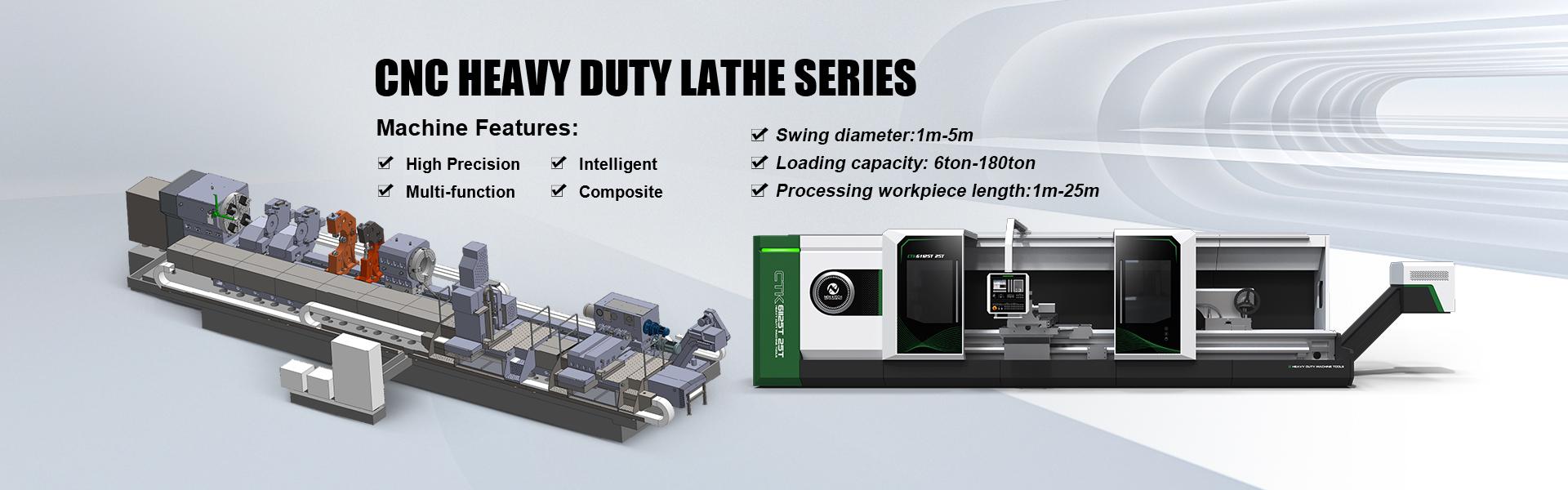
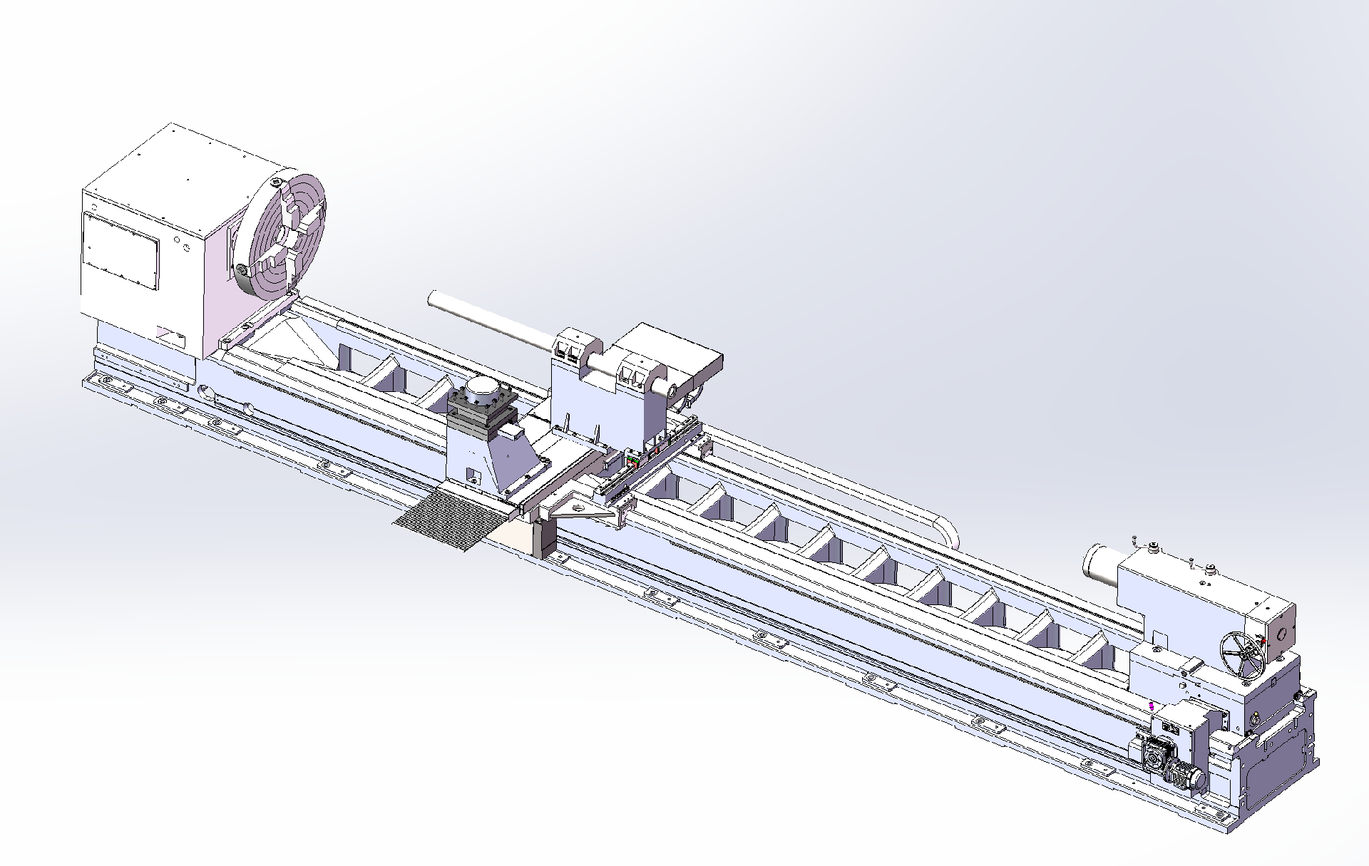
The entire lathe consist of bed, headstock, carriage, tailstock, chuck, cooling system, hydraulic system, protective cover, and electrical system and other main parts. It is capable of turning the outer diameter, end face, chamfer, arc surface, curved surface, groove and threads of shaft-type and disk-type workpiece.
This lathe is a horizontal flat bed CNC lathe, controlled by the SIEMENS 828D CNC system. Which comes standard with a portable handwheel for convenient tool setting and portable control.
The machine bed adopts a "one V and one level + 45 ° hard rail auxiliary guide rail’s structure, with the guide rail surface middle-frequency quenched; The headstock has a hydraulic four-speed gearbox; The tool post is equipped with an electric four-position turret; The tailstock has an upper and lower split structure; and the machine is equipped with semi-enclosed protective cover. Both horizontal-axis and longitudinal-axis transmissions use servo motors paired with precision reducers and ball screw assemblies, with semi-closed-loop control. The main motor can be a 37kW servo spindle motor from Sichuan MK.
Machine operating environment
Ambient temperature 5 ℃ ~ 45
Relative humidity ≤ 85%
Power supply : three-phase 380V ± 10%
Power frequency: 50 HZ ± 2 HZ
|
|
| |
Overall parameters | Max Swing diameter over bed | mm | Φ1250/1450/1650/1850/2050 |
Max swing diameter over tool post | mm | Φ850/1020/1220/1420/1620 | |
Max workpiece length between two center | mm | 1500/2000/3000/4000/5000 | |
Guide Width of lathe | mm | 1100 | |
Max load capacity of chuck and tailstock |
| 10 | |
| Diameter of spindle front support bearing | mm | Φ200 |
Spindle bore taper | Metric Φ140 | ||
Centre angle |
| 60 | |
Spindle head type |
| A2-15 | |
Spindle bore | mm | φ130 (standard) | |
Spindle speed range | r/min | 5-500 (hydraulic fourth gear) | |
Main motor power | kW | AC37 (Sichuan MK) | |
Spindle chuck diameter | mm | Φ1000 manual four-claw single-action | |
| X-axis travel | mm | 750/750/850/950/1050 |
Z-axis travel | mm | 1350/1850/2850/3850/4850 | |
X-axis fast moving speed | mm/min | 4000 | |
Z-axis fast moving speed | mm/min | 4000 | |
X-axis feed motor torque | N.m | 20 SIEMENS | |
Z-axis feed motor torque | N.m | 27SIEMENS | |
Tool cross-section dimensions | mm | 40×40 | |
Turret specifications | mm | 400×400 | |
Vertical four-station tool post brand | Changzhou of china | ||
Tailstock | Sleeve diameter | mm | Φ 260 |
Maximum travel of sleeve | mm | 300 | |
Sleeve moving speed | mm/min | 50 | |
Tailstock quill taper | mm | Metric 80 (with reducing sleeve) | |
Tailstock tip | Mohs 6 # | ||
center angle | Degree | 60 | |
Overall tailstock movement | Electric | ||
|
| mm | 6000/6500/7500/8500/9500×3500×2300 (length without chip evacuator) |
Total power of lathe | kVA | 80KW | |
Geometric accuracy of machine tools | X-axis repeat positioning accuracy | mm | ±0.012 |
Z-axis repeated positioning accuracy | mm | ±0.02/2000 | |
X-axis positioning accuracy | mm | ±0.02 | |
Z-axis positioning accuracy | mm | ±0.025/2000 | |
X-axis reverse deviation | mm | 0.01 | |
Z-axis reverse deviation | mm | 0.03/2000 | |
Machining accuracy of machine tool (national standard test piece) | Dimensional accuracy | IT6-7 | |
Surface roughness | Ra1.6 Planar cylinder | ||
Roundness of finish turning | mm | 0.01 | |
Cylindricity | mm | 0.02/300 | |
Flatness of finished end face | mm | 0.025/300 | |
Machine structure overview
Bed
The bed is a floor-mounted structure width of 1100mm, made of HT300 high-strength resin sand casting. The machine bed has strong rigidity, large load capacity and excellent stability.
The machine tool guideway adopts a "one V-one flat + 45° hardened auxiliary guideway" structure, and is subjected to medium-frequency quenching treatment. The quenching depth is deep, which facilitates secondary grinding of the machine tool.
Inside the bed body, “W”-shaped reinforcing ribs are arranged, connecting all surfaces of the bed into an integral structure, which greatly enhances the rigidity of the machine bed and reduces deformation under load.
After aging treatment, the bed casting has effectively eliminated the residual stresses inside the casting, reducing the release of residual stresses during machining and operation, thereby minimizing bed deformation and the loss of accuracy.
The machine bed casting is designed with a rear chip removal slope and arched openings, allowing chips, coolant, lubricating oil, and other waste to flow directly into the chip tray, making chip removal and cleaning convenient, and enabling the coolant to be recycled for reuse.
.
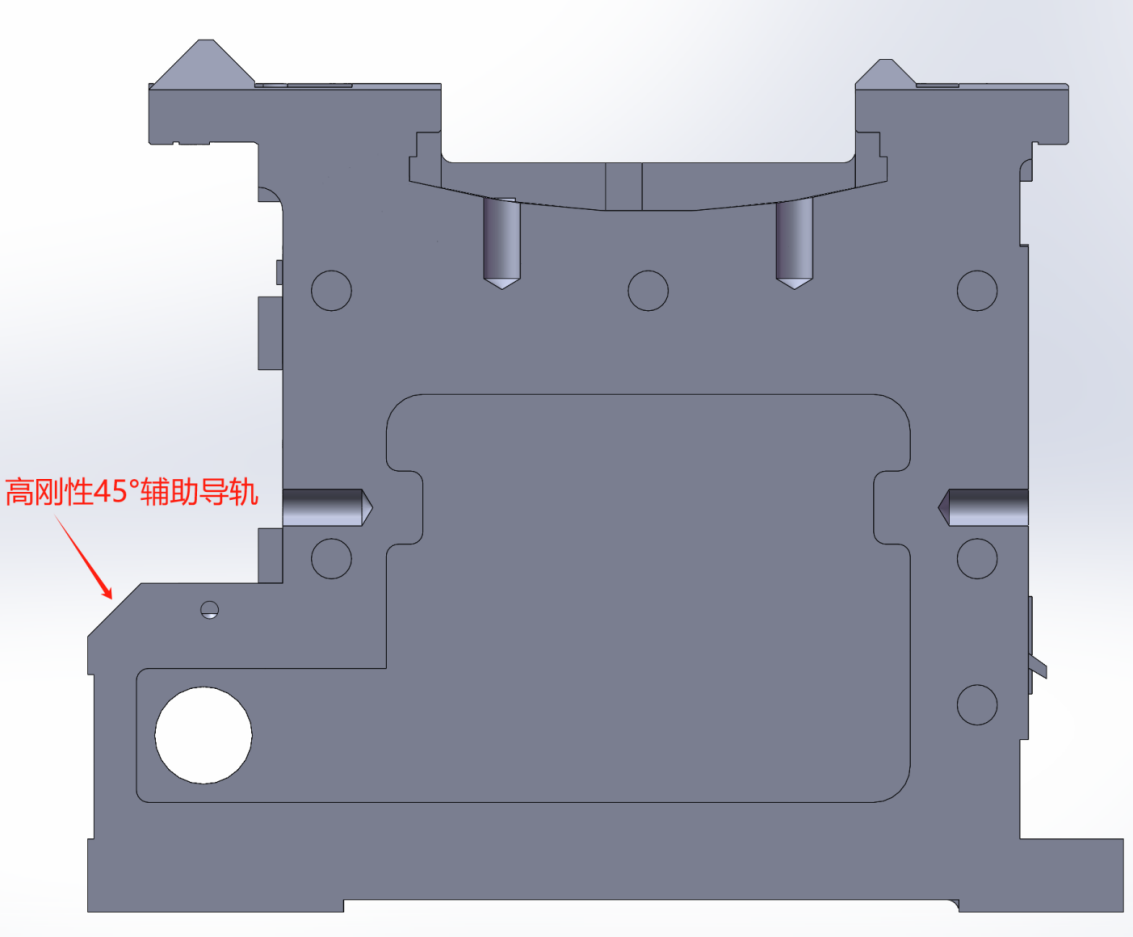
Cross-section view of bed
Headstock
The headstock spindle support adopts a typical and mature three-point bearing structure. The bearings use high-precision spindle bearings from Harbin Bearing (HRB), Wafangdian Bearing (zwz), and Luoyang Bearing Corporation (Luoyang), providing the spindle system with optimal rigidity and load capacity, ensuring smooth rotation and high accuracy. The main motor is a 37 kW spindle-specific AC servo motor, characterized by high torque at low speeds. The spindle speed features four-stage stepless speed regulation, with a speed range of 5–500 r/min. The headstock box employs an external lubrication system, allowing the lubricating oil to be fully cooled during the circulation process. The lubrication pump is a gear pump.
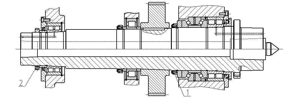
Spindle structure diagram
Saddle and tool post
Adopts a heavy-duty saddle with high rigidity using a boring and turning structure
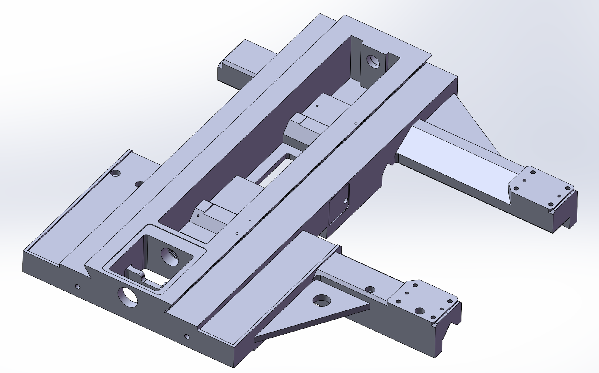
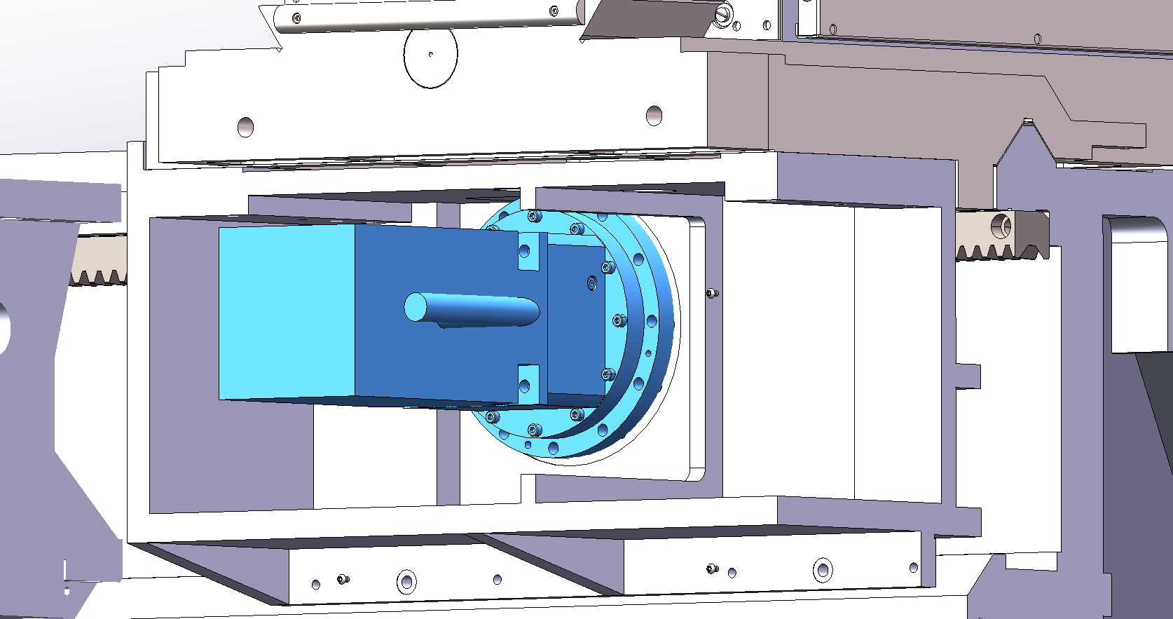
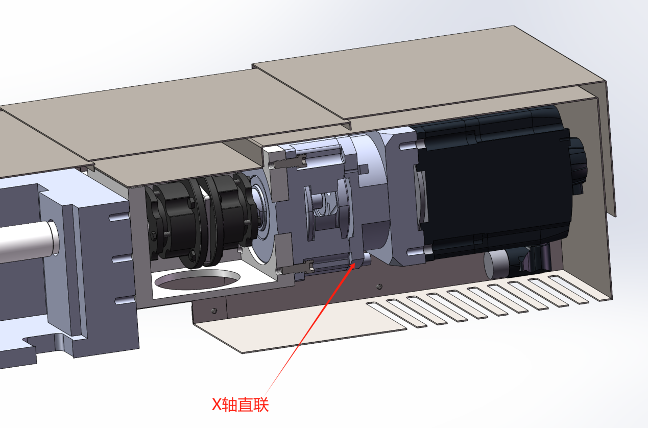
Driven by servo motors, the X and Z axes use ball screw drives. The X-axis ball screw has a diameter of φ50×10, and the Z-axis ball screw has a diameter of φ80×20. Both ends of the ball screws are supported by angular contact ball bearing sets with large contact angles. The support mode is "fixed — tension," which increases the stiffness and operational accuracy of the ball screws.
The tool turret is equipped with a motorized vertical four-station turret, featuring flexible indexing, reliable positioning, and easy operation.
The tool turret is equipped with a vertical four-station turret, featuring flexible indexing, reliable positioning, and easy operation. The turret adopts an internal coolant supply structure.
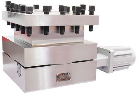
Schematic diagram of turret
Tailstock:
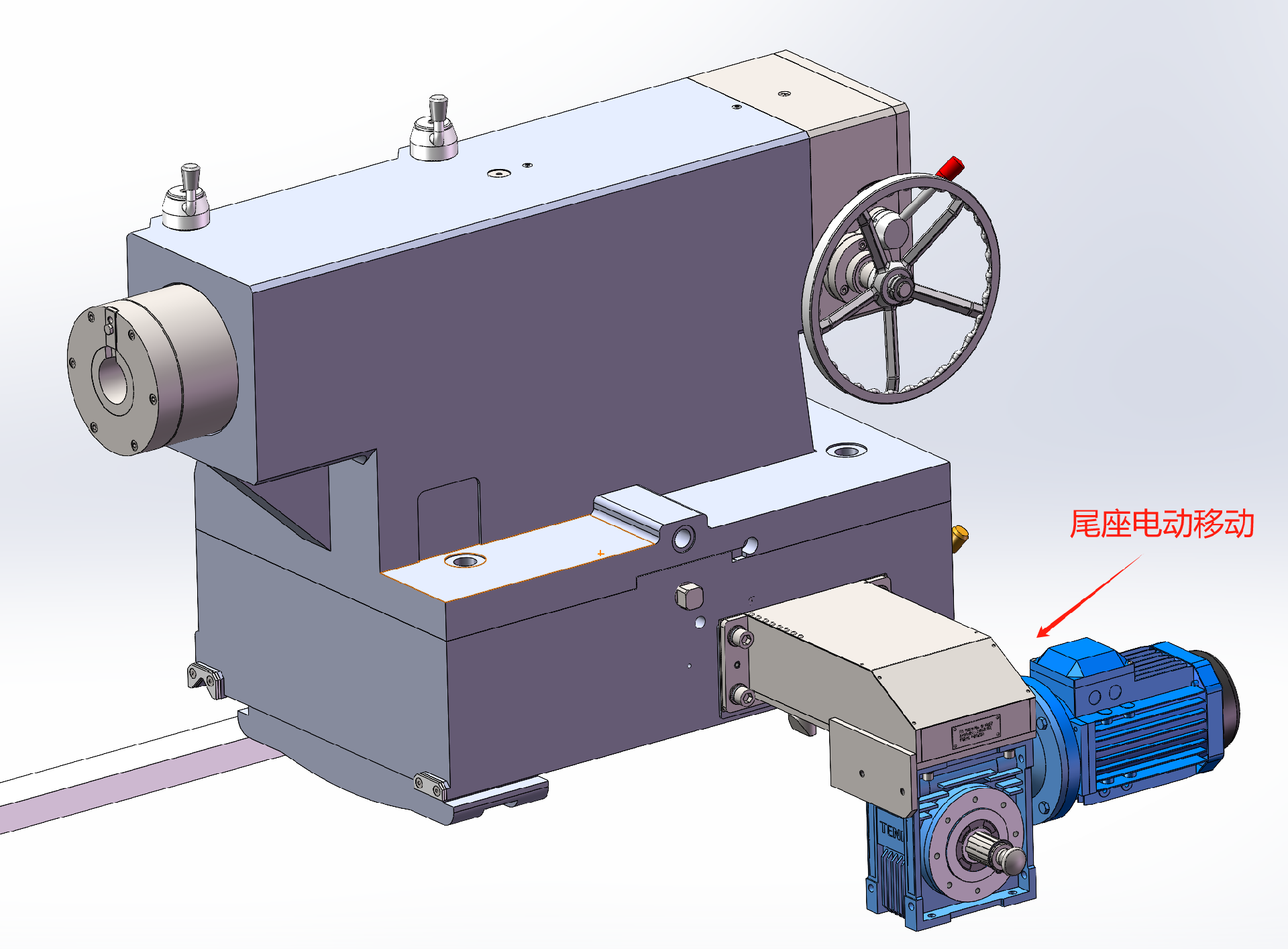
The tailstock of this machine adopts a spindle rotary structure, with a tailstock sleeve diameter reaching φ260 mm, providing sufficient rigidity and load capacity. The tailstock movement is driven by an AC motor through a gear rack, enabling fast and convenient longitudinal movement with excellent operability. The tailstock sleeve is driven by an AC motor via a pinion reducer and a T-type screw, allowing easy clamping and releasing of the workpiece, further enhancing operability. The tailstock consists of two main parts: the upper and lower bodies. The upper body houses the tailstock sleeve, spindle, tailstock sleeve moving mechanism, and spindle center adjustment mechanism. The tailstock spindle bearings use high-precision spindle-specific bearings from Harbin Bearing (HRB), Wafangdian Bearing, and Luoyang Bearing Corporation(zwz), offering strong load capacity, smooth rotation, and high accuracy. The tailstock sleeve and spindle are connected and separated conveniently by a key. When using the center, the key is removed so that the center rotates with the workpiece, preventing relative movement between the workpiece and the center, thereby reducing center wear. A disc spring mechanism is installed at the rear of the tailstock spindle to prevent damage to the tailstock system caused by workpiece thermal expansion. To prevent slipping between the tailstock and the bed during workpiece support, an anti-retreat rod is installed on the tailstock.
Cooling system, chip conveyor
The machine is equipped with a complete cooling system to cool both the workpiece and the cutting tools, helping to protect the workpiece and extend the tool life.At the rear side of the machine, the protective base is equipped with a chain-type automatic chip conveyor system, accompanied by a matching chip collection trolley for convenient centralized chip collection. The water pump is integrated with the chip conveyor, with a head of 16 meters, enabling thorough cooling of the cutting tools.
Steady rest and roller support (optional accessories)
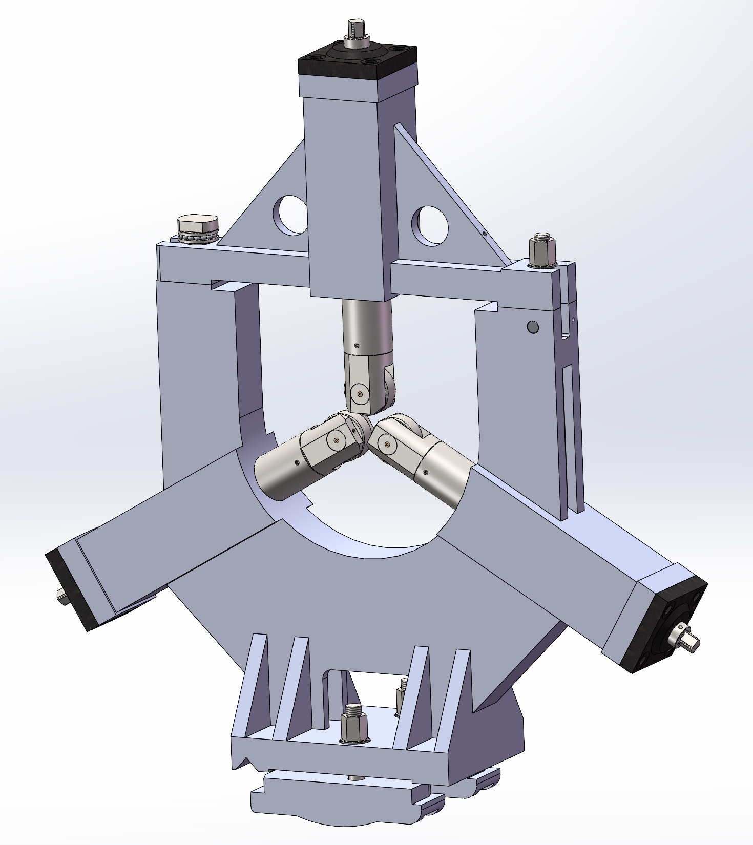
The machine can be optionally equipped with a roller steady rest for workpieces with diameters ranging from φ100 to φ500 mm. Φ450-800mm roller center frame;
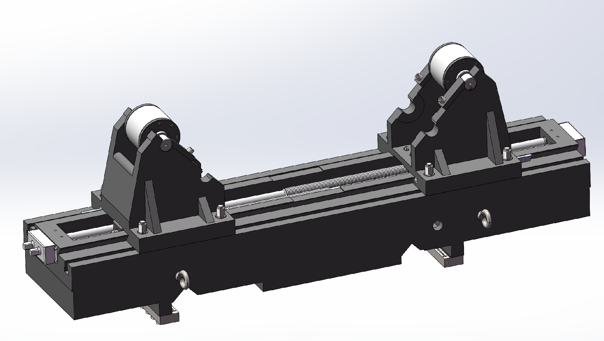
Depending on the characteristics of the workpiece, the machine can be optionally equipped with workpiece roller supports (two-point rollers).
Double Sliding Doors, Semi-Enclosed Protection
The machine can be equipped with double sliding doors for semi-enclosed protection. The machine control box is a separate mobile unit that can freely move along the bed direction without interfering with the sliding doors. The control box can rotate to facilitate real-time observation during operation.
CNC System Configuration
Optional SIEMENS 828D CNC system, including CNC control unit, control amplifier, AC servo motors, with 2-axis linkage. Equipped with spindle encoder.
Features tool shape and tool wear compensation.
Tool radius compensation.
Direct programming using drawing dimensions.
Built-in programmable machine controller.
Supports linear interpolation and circular interpolation functions.
Backlash and pitch error compensation.
Manual electronic handwheel feed..
External computer interfaces.
Single or multi-start thread turning
The machine's electrical cabinet is custom-made, with neatly arranged internal electrical components and reasonable space layout. The machine is equipped with an air-cooled air conditioner to protect against temperature rise inside the electrical cabinet.
Material and heat treatment requirements of main parts
| | | |
1 | Guide rail of machine bed | HT300 | |
2 | | HT200 | |
3 | | HT150 | |
4 | | 45 or 40Cr | |
Detailed list of major purchased parts
| | | | | |
1 | | | Harbin Bearing (HRB) Wafangdian Bearing (ZWZ) Luoyang Bearing (ZYS) | ||
2 | | | | ||
3 | | | | 1 | |
4 | | | | | |
5 | | | | | |
6 | | | | | |
7 | M6 | | | | |
8 | | 400X400 | 1 | | |
9 | | | | ||
10 | | | | ||
11 | | K72/Φ1000 | | |
Basic components of machine tools
| | | |
1 | | | |
2 | Electrical cabinet | | |
3 | | | |
4 | | | |
5 | | | |
Equipment Options List
| | | |
1 | Spindle bearing | NSK/FAG/SKF Brands | |
2 | Heavy-duty four-jaw chuck | K78 Other specifications | |
3 | Electric tool post | Yantai Huanqiu Other Brands | |
4 | Powered turret | BMT75/VDI50 | Taiwan Brand/Germany/Italy |
5 | Simple C-axis indexing | Taiwan hydraulic brake, high-precision encoder, KND main motor, KND2000T system | Must be equipped with optional power turret |
6 | Numerical control system | KND2000T/FANUC System | When selecting the powered turret, it must be equipped with |
7 | Tool setting instrument | Renishaw direct-reading tool setter | |
8 | On-line measurement | Renishaw RLP40 Wireless Probe | |
9 | Special boring tool holder | Φ300/260/200mm reference hole, boring tool seat reducing sleeve, etc | |
10 | Inner bore grinding head | Non-standard, based on workpiece diameter and length | |
11 | Cylindrical grinding head | 1.1 Kw φ300 grinding wheel | |
12 | Tailstock taper, tailstock chuck, etc |
Boring device (optional, selected based on workpiece characteristics)
The machine is equipped with a boring device capable of boring the inner holes of workpieces. The boring device is mounted on a specially widened and thickened slide plate. The rear part of the boring bar is supported by a linear guide installed on the saddle to increase the rigidity of the boring bar. Additionally, counterweights are added to the rear of the boring bar according to processing requirements to ensure machining accuracy. Inside the boring bar, cooling water pipes are installed to cool the cutting tools during machining.
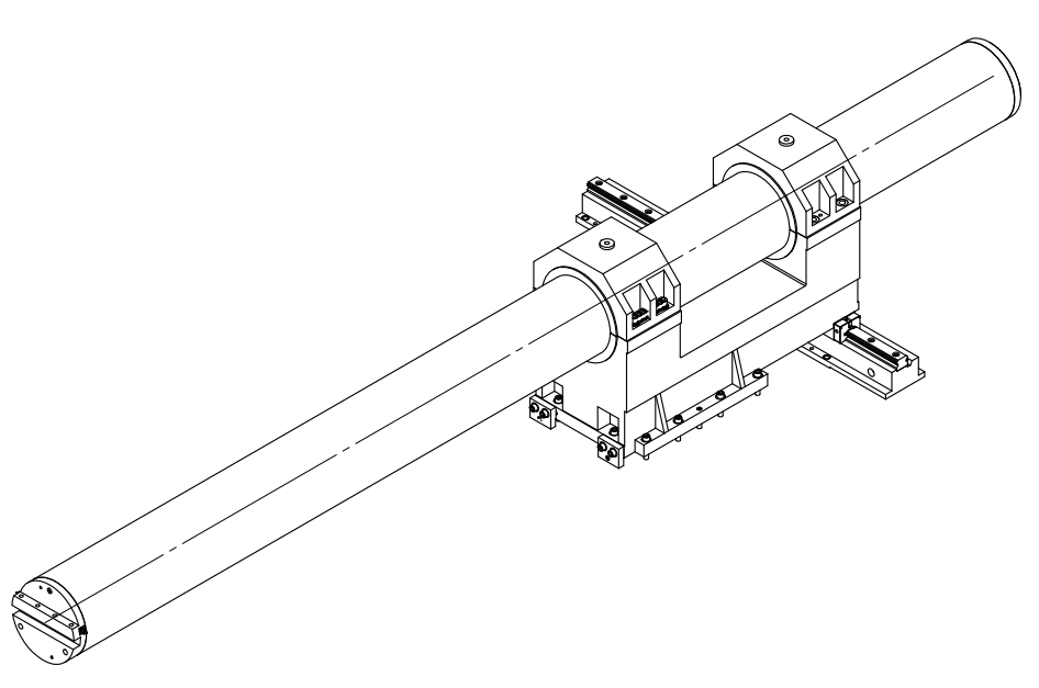
The reference hole of the boring tool holder can reach φ300 mm, equipped with a φ300 mm boring bar with a maximum boring depth of 2400 mm, along with a set of vibration-resistant boring bars.
Product Parameters:

Whatsapp Code


 +86-151 6596 4868
 +86-151 6596 4868
 +86-151 6596 4868
 susan@novatechlathe.com
