



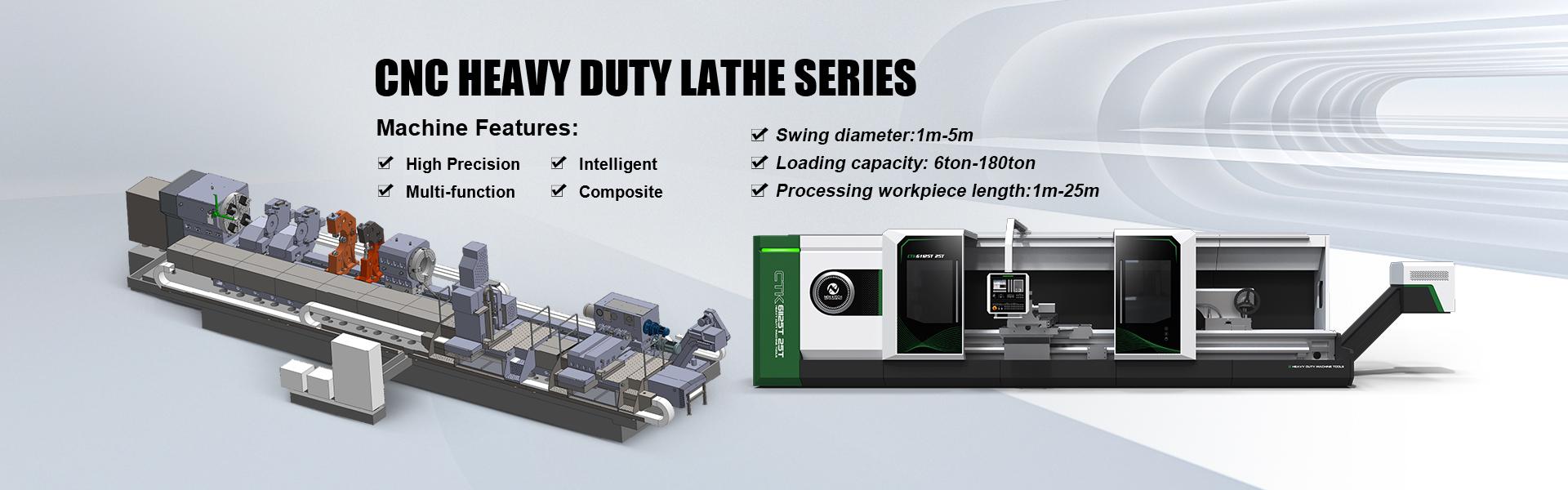
Product Features:
1. Product model and name
CTK61 H series × 1-5M/20T CNC heavy-duty horizontal turning and boring machine
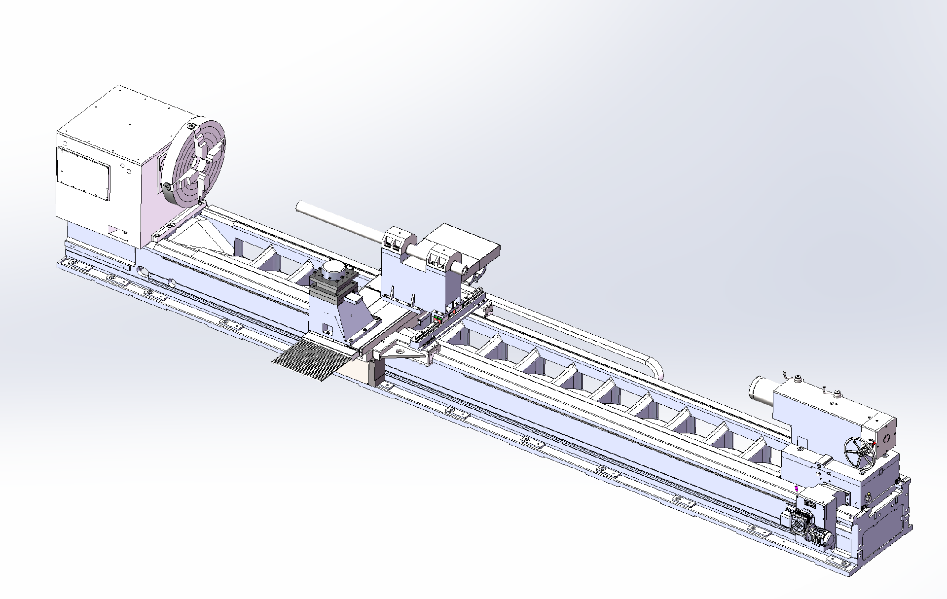
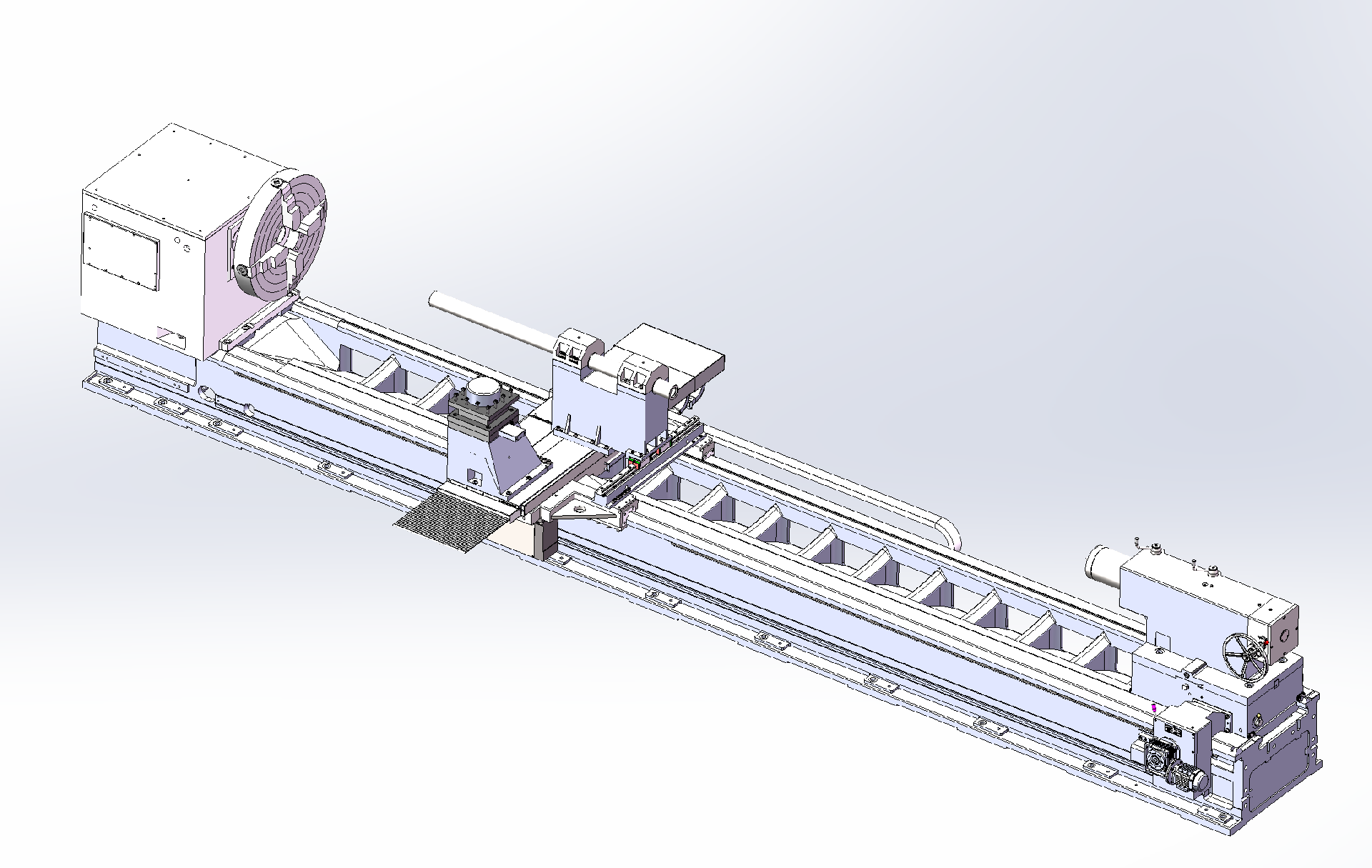
Schematic diagram of machine tool structure
The whole machine tool is composed of bed, Headstock, carriage, tailstock, chuck, cooling, hydraulic station, protection, electrical and other main parts. It can complete the cutting functions of outer circle, end face, inclined surface, arc surface, curved surface, groove and thread of shaft and disk parts.
This machine tool is a horizontal flat bed CNC lathe, which is controlled by SIEMENS 828D CNC system. The CNC system is equipped with a hand wheel as standard, which is convenient for processing tool setting and portable control.
The bed body of the machine tool has a structure of "one V and one Flat + 45 ° hard rail auxiliary guide rail", and the surface of the guide rail is quenched at intermediate frequency; The headstock is hydraulic four-speed variable; The tool holder is equipped with an electric four-station tool holder; Tailstock upper and lower split structure; Equipped with semi-enclosed guards. The horizontal and longitudinal transmission of the machine tool adopts servo motor plus precision reducer with ball screw pair transmission and semi-closed loop control. The main motor can be driven by Sichuan Emke 37kW servo spindle motor.
Ambient temperature 5 ℃ ~ 45 ℃
Relative humidity ≤ 85%
Power supply system: three-phase 380V ± 10%
Power frequency: 50 HZ ± 2 HZ
Units | Parameters | ||
Overall parameters | Maximum swing diameter over bed | mm | Φ 1250/1450/1650/1850/2050 |
Maximum swing diameter over tool holder | mm | Φ 850/1020/1220/1420/1620 | |
Maximum workpiece length between two centers | mm | 1500/2000/3000/4000/5000 | |
Guide Width of Machine Tool | mm | 1100 | |
Maximum load bearing of chuck and tailstock | Tonnes | 20 | |
Spindle | Diameter of spindle front support bearing | mm | Φ 240 |
Spindle bore taper | Metric Φ160 | ||
Apex angle | Degree | 60 | |
Spindle head form | Specifications | 1:30 long cone | |
Spindle via | mm | φ150 (standard) | |
Spindle speed range | r/min | 5-315 (hydraulic fourth gear) | |
Main motor power | kW | AC37 (Sichuan Emke) | |
Spindle chuck diameter | mm | Φ1000 heavy-duty manual four-claw single-action | |
Tool holder | X-axis travel | mm | 750/750/850/950/1050 |
Z-axis travel | mm | 1350/1850/2850/3850/4850 | |
X-axis fast moving speed | mm/min | 4000 | |
Z-axis fast moving speed | mm/min | 4000 | |
X-axis feed motor torque | N.m. | 20 SIEMENS | |
Z-axis feed motor torque | N.m. | 36 SIEMENS | |
Tool cross-section dimensions | mm | 40×40 | |
Turret specifications | mm | 400×400 | |
Vertical four-station tool holder brand | Changzhou | ||
Tailstock | Sleeve diameter | mm | φ300 |
Maximum travel of sleeve | mm | 300 | |
Sleeve moving speed | mm/min | 50 | |
Mandrel taper | mm | Metric 80 (with reducing sleeve) | |
Tailstock tip | Mohs 6 # | ||
Apex angle | Degree | 60 | |
Overall tailstock movement | Electric | ||
Weight and Diamension | Overall dimensions (L × W × H) | mm | 6000/6500/7500/8500/9500 × 3500 × 2300 (length without chip evacuator) |
Total power of machine tool | kVA | 80KW | |
Geometric accuracy of machine tools | X-axis repeat positioning accuracy | mm | ±0.012 |
Z-axis repeated positioning accuracy | mm | ±0.02/2000 | |
X-axis positioning accuracy | mm | ±0.02 | |
Z-axis positioning accuracy | mm | ±0.025/2000 | |
X-axis reverse deviation | mm | 0.01 | |
Z-axis reverse deviation | mm | 0.03/2000 | |
Machining accuracy of machine tool (national standard test piece) | Dimensional accuracy | IT6-7 | |
Surface roughness | Ra1.6 Planar cylinder | ||
Roundness of finish turning | mm | 0.01 | |
Cylindricity | mm | 0.02/300 | |
Flatness of finished end face | mm | 0.025/300 | |
5. Introduction to the main structure of the machine tool
5.1 Bed
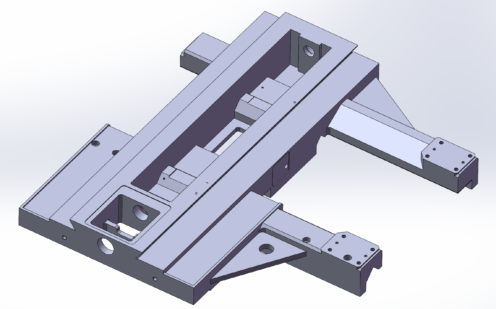
The bed body of the machine tool is a floor-standing bed with a width of 1100mm. It is cast with high-strength resin sand and the material is HT300. The machine tool bed has strong rigidity, large bearing capacity and good stability.
The machine tool guide rail has a structure of "oneV, one flat+ 45 ° hard rail auxiliary guide rail", and is subjected to intermediate frequency quenching treatment. The quenching depth is deep, which is conducive to the secondary regrinding of the machine tool.
The inner cavity of the bed body is provided with "W"-shaped reinforcing ribs, which connect all surfaces of the bed body into a whole, greatly strengthening the rigidity of the machine tool bed body and reducing stress deformation.
After the aging of the bed casting, the residual stress inside the casting is well removed, which reduces the release of residual stress, reduces the deformation of the bed and reduces the precision of the machine tool during processing and use.
The machine tool bed is cast with a slope and an arch door for rearward chip removal, so that chips, coolant, lubricating oil, etc. can be directly discharged into the chip receiving tray, which is convenient for chip removal and cleaning, and the coolant can also be recycled and reused.
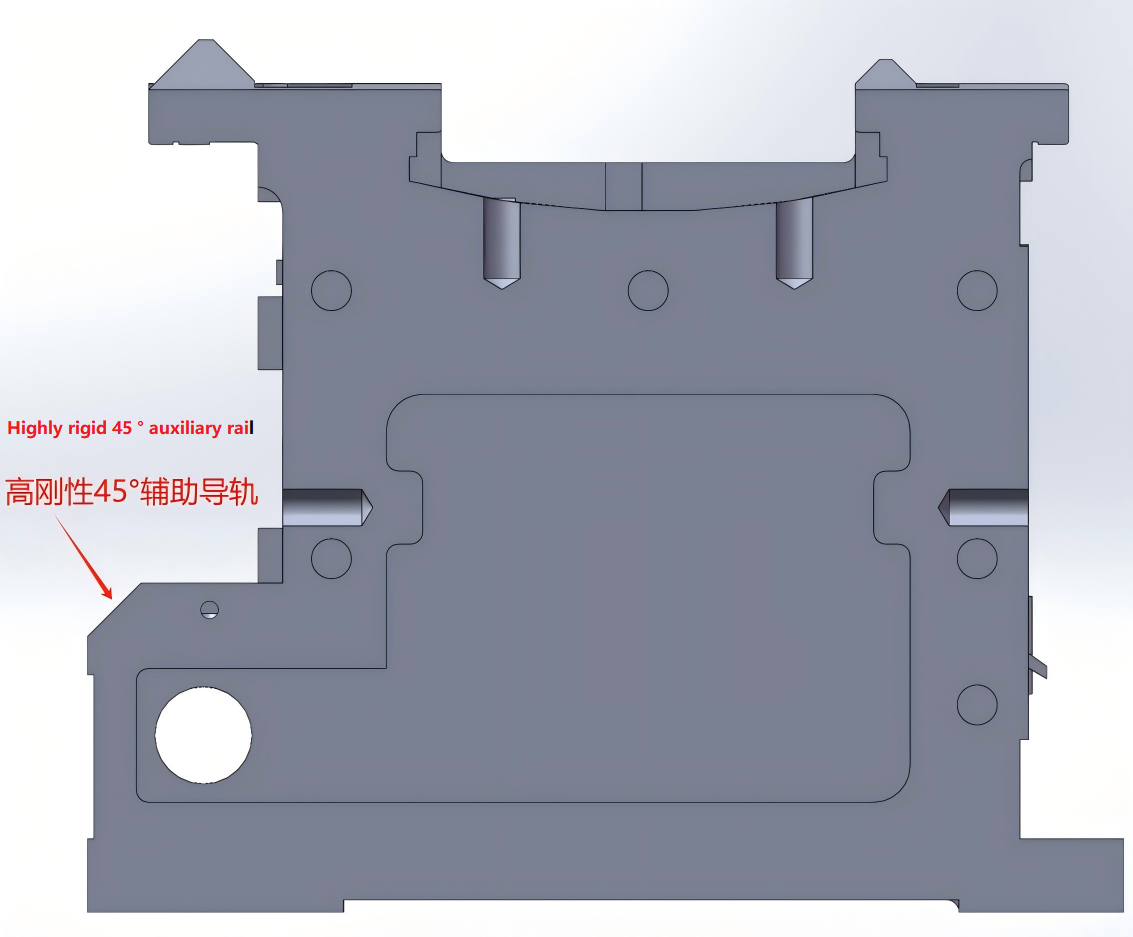
Cross-section view of bed
5.2 Headstock
The headstock spindle support adopts a typical and mature three-support structure, and the bearings adopt HRB,ZWZ high-precision spindle bearings, which makes the spindle system have the best stiffness and load-bearing capacity, smooth rotation and high precision. The main motor is a 37 kW spindle-specific AC servo motor, which has the characteristics of high torque at low speed. The rotational speed of the spindle is four-speed stepless speed regulation, and the rotational speed range is 5-315 r/min. The bedside box is lubricated outside the box, and the lubricating oil can be fully cooled during the circulation process. The lubricating pump is a gear pump.
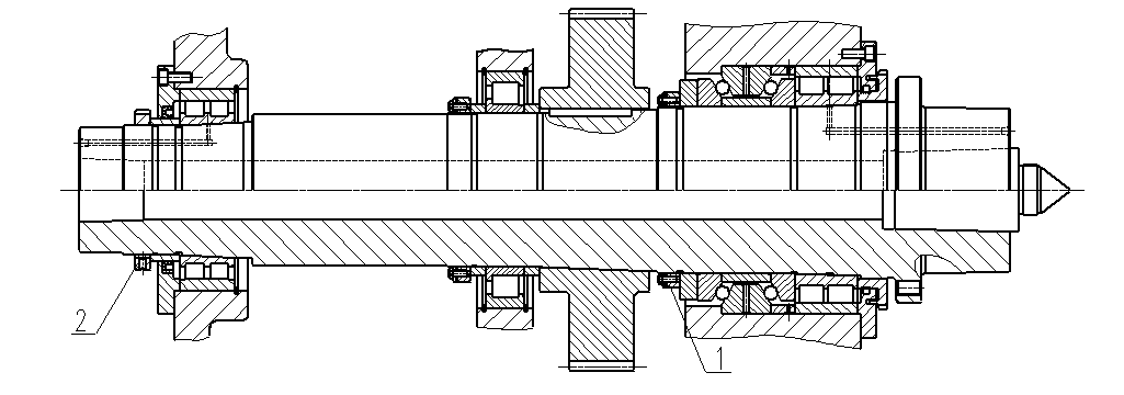
Spindle structure diagram
5.3 Trailer and tool holder
It adopts a turning boring structure with high rigidity heavy-duty carriage.
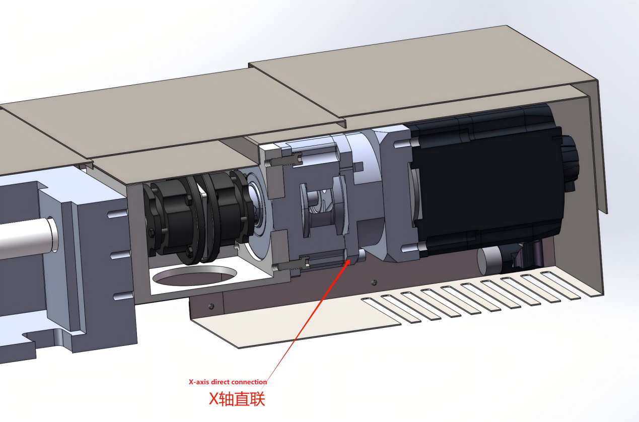
It is driven by servo motor, and the X-axis and Z-axis transmissions are ball screw pair transmissions. The diameter of the X-direction ball screw is φ50x10, and the diameter of the Z-direction ball screw is φ80x20. Both ends of the ball screw are supported by angular contact ball bearing groups with large contact angles. The support mode is "fixed-stretched", which can increase the motion stiffness and running accuracy of the screw.
The tool holder is equipped with an electric vertical four-station rotary tool holder, which has flexible indexing, reliable positioning and easy operation.
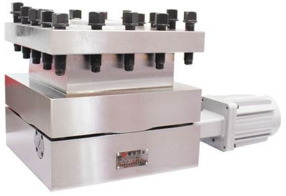
Schematic diagram of turret
5.4 Tailstock:
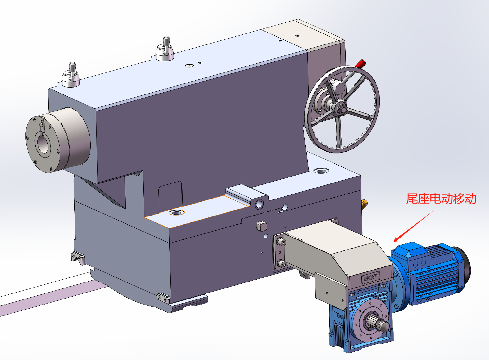
The tailstock of this machine tool is a mandrel rotary structure, and the diameter of the tailstock sleeve reaches φ300mm, which has sufficient rigidity and bearing capacity. The movement of the tailstock is driven by the AC motor to move longitudinally through the rack and pinion, and the movement of the tailstock is convenient, quick and pleasant. The tailstock sleeve is driven by an AC motor through a pinwheel reducer and a T-shaped screw, which can conveniently tighten and loosen the working parts, which is more pleasant. The tailstock consists of an upper body and a lower body, and the upper body of the tailstock is provided with a tailstock sleeve, a mandrel, a tailstock sleeve moving mechanism and a spindle center adjusting mechanism. The tailstock spindle bearing adopts HRB,ZWZ high-precision spindle special bearings, which have strong bearing capacity, smooth rotation and high precision. The tailstock sleeve and the mandrel are conveniently separated and connected by a plug key. When using the tip, take out the insert key to make the tip rotate with the workpiece, so as to avoid the wear of the tip caused by relative movement between the workpiece and the tip. A disc spring mechanism that prevents damage to the tail shaft system due to thermal expansion of the workpiece is installed behind the tail shaft. In order to prevent sliding between the tail end of the bed and the bed body when holding the workpiece, a retraction lever is installed on the tail stock. The tailstock is equipped with a dynamometer, which can display and set the tightening force of the tailstock according to the weight of the workpiece.
5.5 Cooling system, chip conveyor
The machine tool is equipped with a complete set of cooling system to cool the workpiece and tool, and protect the workpiece and prolong the service life of the tool.
On the rear side of the machine tool, the protective bottom is equipped with a set of chain plate automatic chip removal machine and a matching chip collection trolley, which facilitates the centralized collection of chips; The water pump is integrated into the chip removal machine with a lift of 16m, which can fully cool the first tool.
5.6 Center frame, tow roller (optional on demand)
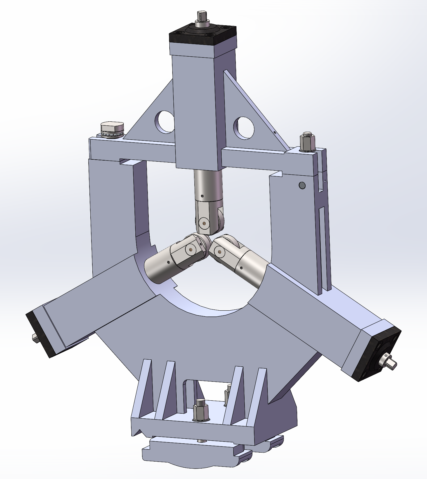
The machine tool can be equipped with an optional center frame φ100-500mm roller center frame;
Φ450-800mm roller center frame;
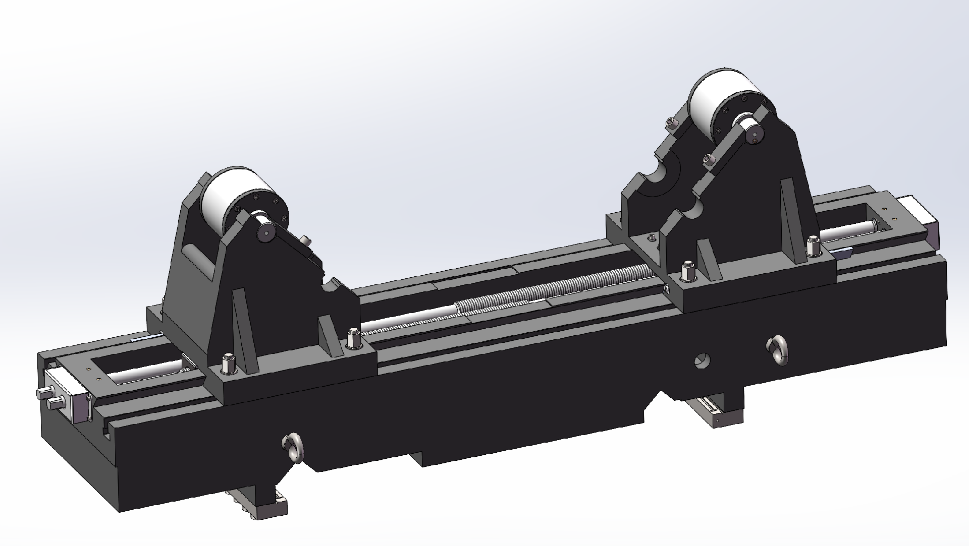
According to the characteristics of the workpiece, the machine tool can be equipped with a workpiece drag roller (two-point roller).
5.7 Double sliding door, semi-closed protection
The machine tool can be equipped with double sliding door semi-closed protection, and the separate moving unit of the machine tool control box can move freely along the direction of the bed without interfering with the sliding door; The control box can rotate at an angle, which is convenient for real-time observation during operation;
6. CNC system configuration:
6.1 SIEMENS 828D numerical control system, CNC control unit, control amplifier and AC servo motor can be selected, and the number of linkage axes is 2 axes. With spindle encoder.
6.2 With tool shape and tool wear compensation.
6.3 Tool radius compensation.
6.4 Direct drawing size programming.
6.5 built-in programmable machine tool controller.
6.6 It has linear interpolation and circular interpolation functions.
6.7 Reverse clearance, pitch error compensation.
6.8 Manual electronic handwheel feed.
6.9 External computer interfaces.
6.10 Single thread or multi thread turning.
6.11 The electric cabinet of the machine tool is a self-made product, with neatly arranged internal electrical components and reasonable space. The machine tool is equipped with an air-cooled air conditioner to protect the temperature rise of the electric box.
7. List of accessories and tools
Serial number | Name | Model and size | Units | Quantity | Remarks |
1 | Four-jaw chuck | Sleeve | 1 | ||
2 | Spindle tip sleeve | Piece | 1 | ||
3 | Tailstock top sleeve | Piece | 1 | ||
4 | Tool holder wrench | Piece | 1 | ||
5 | Chuck wrench | Piece | 1 | ||
6 | Chuck plate | Piece | 1 | ||
7 | Spindle tip | Piece | 1 | ||
8 | Tailstock tip | Piece | 1 | ||
9 | Double-ended wrench | 8 × 10 S91-1 | Piece | 1 | |
10 | Double-ended wrench | 12 × 13 S91-1 | Piece | 1 | |
11 | Double-ended wrench | 27 × 30 S91-1 | Piece | 1 | |
12 | Double-ended wrench | 32 × 36 S91-1 | Piece | 1 | |
13 | Double-ended wrench | 41 × 46 S91-1 | Piece | 1 | |
14 | Single-headed wrench | 16 S91-2A | Piece | 1 | |
15 | Single-headed wrench | 18 S91-2A | Piece | 1 | |
16 | Single-headed wrench | 21 S91-2A | Piece | 1 | |
17 | Single-headed wrench | 24 S91-2A | Piece | 1 | |
18 | Allen wrench | 6 S91-7 | Piece | 1 | |
19 | Allen wrench | 8 S91-7 | Piece | 1 | |
20 | Allen wrench | 10 S91-7 | Piece | 1 | |
21 | Allen wrench | 12 S91-7 | Piece | 1 | |
22 | Allen wrench | 14 S91-7 | Piece | 1 | |
23 | Allen wrench | 22 S91-7 | Piece | 1 | |
24 | Hook wrench | 270-310 S93-1 | Piece | 1 | |
25 | Hook wrench | 330 S93-1 | Piece | 1 | |
26 | Hook wrench | 400 S93-1 | Piece | 1 | |
27 | Pliers for elastic retaining ring | 3.0 S94-1A | Piece | 1 | |
28 | Single-headed wrench | 55 | Piece | 1 | |
29 | Chuck seat wrench | Piece | 1 | ||
30 | Roller center frame | Φ100-φ500mm | Sleeve | Optional | |
31 | Roller center frame | Φ450-φ800mm | Sleeve | Optional | |
32 | Workpiece drag roller | Φ400-φ850mm/ Φ600-φ1050mm/ Φ800-φ1250mm/ Φ1000-φ1450mm/ Φ1000-φ1450mm | Sleeve | Optional |
8、Material and heat treatment requirements of main parts
Serial number | Name | Material | Heat treatment process |
1 | Bed rail | HT300 | Thermal aging of bed, vibration aging after rough machining; Intermediate frequency quenching of bed guide rail |
2 | Headstock | HT200 | Thermal aging, vibration aging after roughing |
3 | Tailstock | HT150 | Thermal aging |
4 | Primary gear | 45 or 40Cr | High frequency quenching, grinding |
9、Detailed list of major purchased parts
Serial number | model | Name | Specifications | Number of pieces | remark |
1 | Spindle bearing | 1 set | HRB,ZWZ | ||
2 | Screw bearing | Sleeve | NSK | ||
3 | 37kW | AC servo motor | 1000 r/min | 1 | MK |
4 | X, Z axis servo motors | 20/36 N.m | 1 set | SIEMENS | |
5 | Numerical control system | SIEMENS 828D | 1 set | SIEMENS | |
6 | Φ 50 × 10 | X-direction ball screw | 1 set | Taiwan | |
7 | Φ 80 × 20 | Z-direction ball screw | 1 set | Nanjing famous | |
8 | Four-station electric tool holder | 400X400 | 1 | Changzhou Hongda/Wenling | |
9 | Main electrical components | 1 set | Schneider | ||
10 | X, Z axis reducer | 1 set | Newstart or equivalent | ||
11 | Manual chuck | K78/Φ1000 | 1 set | Wafangdian |
10. Basic components of machine tools
Serial number | Name | Drawing No. and Specification | Quantity | Remarks |
1 | Mainframe | 1 unit | Comprises a control element, a fast motor | |
2 | Electrical cabinet | 1 unit | ||
3 | Cooling tank system | 1 set | ||
4 | Illumination device | 1 set | On the host | |
5 | Random attachment | See instructions | In the accessory box |
11. Other disassembly parts
Serial number | Name | Model number | Specifications | Number of pieces |
1 | Anchor bolt | GB799-88 | M 30 × 600 | 1 set |
2 | Hex nut (rough) | GB41-86 | M30 | 1 set |
3 | Flat Washer (Class C) | GB95-85 | 30 | 1 set |
4 | Set screw | GB83-88 | M24X80 |
12. Random technical documents
Serial number | File Name | Remarks |
1 | Instructions for Use | |
2 | Factory Certificate of Conformity | Includes accuracy check record sheet |
3 | Packing list |
13. Acceptance of machine tools
13.1 Pre-acceptance of machine tools
113.1. 1 Pre-acceptance shall be carried out at the manufacturer, and the acceptance item shall be accuracy inspection. Fill in the "Inspection Record Sheet" and use it as the basis for final acceptance.
13.1.2 The inspection tools for pre-acceptance shall be provided by the manufacturer.
13.2 Machine tool installation and commissioning and responsibilities of both parties
After the contract comes into effect, the manufacturer shall provide the user with the installation condition drawing of the machine tool foundation, and the user shall be responsible for the design and construction of the foundation, and at the same time complete the power connection of the equipment and the placement of the equipment after receipt. The manufacturer shall send personnel to guide the installation of the equipment and be responsible for calibration, debugging and commissioning. The user shall cooperate with the manufacturer to complete the debugging work.
13.3 Final acceptance of machine tool
13.3.1 After the equipment installation and commissioning is completed, the final acceptance shall be carried out by the user;
13.3.2 Trial processing of national standard workpieces to meet the requirements of the agreement, sign the final acceptance minutes, and both parties sign and approve them.
13.3.3 The inspection tool test pieces for final acceptance shall be provided by the user.
14. Training
The manufacturer trains the operation and maintenance personnel free of charge for the user, and the specific training contents are as follows:
The training is conducted in two sessions, the first one during the pre-acceptance period, i.e. at the manufacturer's site. The second time is carried out during the final acceptance period, that is, at the user's site. The number of participants in the training is 3-5 people.
15. Quality assurance and after-sales service
15.1 The quality guarantee period of the machine tool is one year from the final acceptance. During this period, if there are quality problems under normal use conditions, the manufacturer is responsible for repairing and replacing the damaged parts free of charge.
15.2 During the warranty period, if the machine tool fails, the manufacturer shall respond within 48 hours after receiving the notice from the user, or send personnel to the user's site for effective treatment.
15.3 After the expiration of the warranty period of the machine tool, the manufacturer shall provide maintenance services to the user at the best price.
Equipment Options List
Serial number | File Name | Optional content | Remarks |
1 | Spindle bearing | NSK/FAG/SKF Brands | |
2 | Heavy-duty four-jaw chuck | K78 Other specifications | |
3 | Electric tool holder | Yantai Global/Other Brands | |
4 | Powered turret | BMT75/VDI50 | Taiwan Brand/Germany/Italy |
5 | Simple C-axis indexing | Taiwan hydraulic brake, high-precision encoder, KND main motor, KND2000T system | Must be equipped with optional power turret |
6 | Numerical control system | KND2000T/FANUC System | Must be equipped with optional power turret |
7 | Tool setting instrument | Renishaw straight arm tool setting instrument | |
8 | On-line measurement | Renishaw RLP40 Wireless Probe | |
9 | Special boring tool seat | Φ300/260/200mm reference hole, boring tool seat reducing sleeve, etc | |
10 | Inner bore grinding head | Non-standard according to the diameter and length of workpiece | |
11 | Cylindrical grinding head | 1.1 Kw φ300 grinding wheel | |
12 | Tailstock taper, tailstock chuck, etc |
Boring device (optional according to workpiece characteristics)
This machine tool is equipped with a boring device, which can bore the inner hole of the workpiece. The boring device is installed on a special slide plate that has been widened and thickened. The rear of the boring bar is supported using linear guides mounted on the carriage to increase the rigidity of the boring bar. The rear part of the boring bar also adds a counterweight according to the machining situation to ensure the machining accuracy. The boring bar is equipped with a cooling water pipe inside for cooling the machining tool.
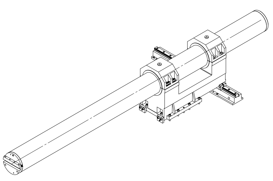
The reference hole of the boring tool seat can be φ300mm, and a set of seismic boring bars with φ300 boring depth up to 2400mm;
Product Parameters:

Whatsapp Code


 +86-151 6596 4868
 +86-151 6596 4868
 +86-151 6596 4868
 susan@novatechlathe.com
