



Product Features:
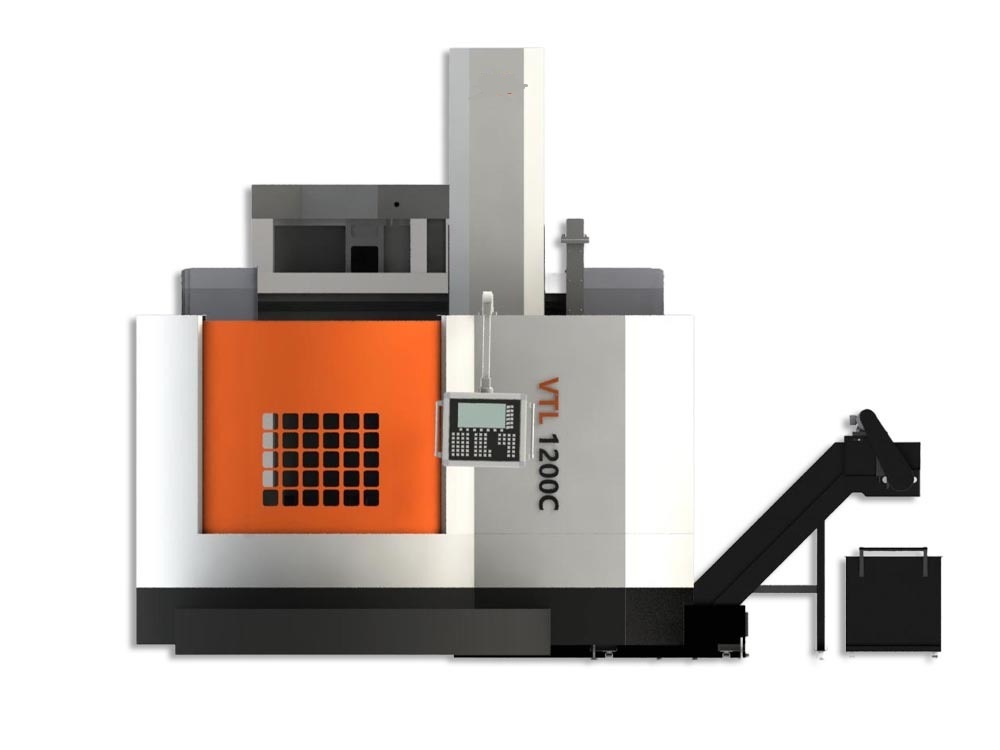
The floor-mounted machine equipment, based on a unique design concept, effectively absorbs heat and isolates vibration through the injection-molded joint surface between the column and base. The machine employs a vertical spindle main drive system, where the gears inside the headstock are hardened through a quenching process. It features a two-range stepless speed variation function, and an encoder is integrated at the spindle center to enable constant surface speed cutting operations.
This floor-mounted machine tool incorporates a unique design concept, utilizing an injection-molded joint surface between the column and base to effectively absorb heat and isolate vibrations. The equipment adopts a vertical spindle main drive system, with gears in the headstock undergoing quenching treatment. It features two-range stepless speed variation functionality and is equipped with an encoder at the spindle center to enable constant surface speed cutting operations.
The machine's crossbeam can be freely positioned within the column's travel range according to requirements, offering user-friendly convenience for operation. Additionally, the wear-resistant plate design on the tool carrier's X and Z axes, combined with quenched guideway surfaces, enhances the wear resistance of the ram surface while extending the service life of the guideways and maintaining high precision.
Integrating mechanical, electrical, and hydraulic systems, the machine features a compact circular protective structure that effectively reduces the footprint, facilitates transportation and installation, and shortens the installation and commissioning time. The crossbeam and vertical tool carrier are pre-equipped with mounting positions for grating scales to ensure precise control of the equipment.
To meet diverse user needs, the machine offers various optional accessories, such as Yantai Universal tool turrets and twelve-station follow-up tool magazines. The inclusion of these options not only improves machining efficiency but also further enhances the machine's performance and application scope.
In summary, this equipment not only delivers efficient and stable performance but also embodies user-centric design principles and excellent manufacturing craftsmanship. It represents an ideal choice for both new equipment procurement and existing facility upgrades.
| No. | Main Technical Parameters | Model | Unit | ||||||||||
|---|---|---|---|---|---|---|---|---|---|---|---|---|---|
| VTL1000 | VTL1200 | VTL1600 | VTL2000 | VTL2500 | VTL3000 | VTL3500 | VTL4000 | VTL4500 | VTL5000 | VTL5500 | |||
| 1 | Table Diameter | mm | 1000 | 1250/1400 | 1600/1800 | 2000 | 2500 | 3000 | 3500 | 4000 | 4500 | 5000 | 5500 |
| 2 | Max. Swinging Diameter | mm | 1250 | 1600 | 2000 | 2500 | 3000 | 3500 | 4000 | 4500 | 5000 | 5500 | 6000 |
| 2 | Max. Turning Diameter | mm | 1250 | 1600 | 2000 | 2500 | 3000 | 3500 | 4000 | 4500 | 5000 | 5500 | 6000 |
| 3 | Max. Workpiece Height (H) | mm | 1000 | 1200 | 1200 | 1400/1600 | 2000/2500 | 2000/2500 | 2500/3100 | 2500/3100 | 2500/3100 | 2500/3100 | 2500/3100 |
| 4 | Max. Workpiece Weight (W) | t | 5 | 8 | 12 | 16 | 20 | 20 | 32 | 32 | 32 | 50 | 50 |
| 5 | Max. Cutting Force (Vertical Tool Post) | kN | 20 | 20 | 25 | 25 | 35 | 35 | 35 | 35 | 35 | 35 | 35 |
| 6 | Max. Worktable Torque | kN·m | 10 | 12.5 | 20 | 25 | 32 | 32 | 50 | 50 | 80 | 80 | 80 |
| 7 | Worktable Speed Stages | II Ranges, Stepless | II Ranges, Stepless | II Ranges, Stepless | II Ranges, Stepless | II Ranges, Stepless | II Ranges, Stepless | II Ranges, Stepless | II Ranges, Stepless | II Ranges, Stepless | II Ranges, Stepless | II Ranges, Stepless | |
| 8 | Worktable Speed Range | mm/min | 1-350 | 1-300 | 1-250 | 1-200 | 1-160 | 1-160 | 1-80 | 1-80 | 1-50 | 1-50 | 1-50 |
| 9 | Vertical Tool Post Feed Rate Stages | Stepless | Stepless | Stepless | Stepless | Stepless | Stepless | Stepless | Stepless | Stepless | Stepless | Stepless | |
| 10 | Vertical Tool Post Feed Rate Range | mm/min | 1-1000 | 1-1000 | 1-1000 | 1-1000 | 1-1000 | 1-1000 | 1-1000 | 1-1000 | 1-1000 | 1-1000 | 1-1000 |
| 11 | Rapid Traverse Rate (Tool Post) | mm/min | 10000 | 10000 | 10000 | 10000 | 6000 | 6000 | 6000 | 6000 | 6000 | 6000 | 6000 |
| 12 | Vertical Travel of Ram (Z-axis) | mm | 800 | 800 | 1000 | 1000 | 1250 | 1250 | 1400 | 1400 | 1400 | 1400 | 1400 |
| 13 | Ram Cross-section | mm | 200x200 | 200x200 | 220x220 | 220x220 | 240x240 | 240x240 | 240x240 | 240x240 | 240x240 | 240x240 | 240x240 |
| 14 | Min. Passable Diameter (Ram) | mm | Φ300 | Φ300 | Φ320 | Φ320 | Φ350 | Φ350 | Φ350 | Φ350 | Φ350 | Φ350 | Φ350 |
| 15 | Tool Magazine Capacity | Tools | 12 | 12 | 12 | 12 | 12 | 12 | 12 | 12 | 12 | 12 | 12 |
| 16 | Tool Shank Type | BT50 | BT50 | BT50 | BT50 | BT60 | BT60 | BT60 | BT60 | BT60 | BT60 | BT60 | |
| 17 | Tool Size | mm | □32 | □32 | □32 | □32 | □32 / □40 | □32 / □40 | □32 / □40 | □32 / □40 | □32 / □40 | □32 / □40 | □32 / □40 |
| 18 | Feed Motor Torque (X/Z) | N·m | 22 | 22 | 22/27 | 22/27 | 30 | 30 | 40/30 | 40/30 | 40/30 | 40/30 | 40/30 |
| 19 | Feed Motor Power (X/Z) | kW | 3.55 | 3.55 | 3.55/4 | 3.55/4 | 5.5 | 5.5 | 6.4/5.5 | 6.4/5.5 | 6.4/5.5 | 6.4/5.5 | 6.4/5.5 |
| 20 | Max. Crossbeam Travel | mm | 750 | 1000 | 1000 | 1200 | 1500 | 1500 | 2100 | 2100 | 2100 | 2100 | 2100 |
| 21 | Main Motor Power (AC Servo) | kW | 37 | 37 | 45 | 45 | 66 | 66 | 66 | 66 | 90 | 90 | 90 |
| 22 | Crossbeam Lifting Motor Power | kW | 2.2 | 2.2 | 5.5 | 7.5 | 11 | 11 | 18.5 | 18.5 | 18.5 | 18.5 | 18.5 |
| 23 | Total Power Capacity | kVA | 50 | 50 | 62 | 65 | 95 | 95 | 100 | 100 | 125 | 125 | 125 |
| 24 | Machine Weight | t | 17 | 20 | 28 | 34 | 48 | 55 | 76 | 83 | 90 | 102 | 115 |
Standard Configuration:
Manual Four-Jaw Chuck Worktable
CNC System (SINUMERIK 828D)
Cabinet Air Conditioner
12-Station Tool Magazine
Cooling System
Maintenance Tools
Standard Tool Holders (2 pcs)
Work Lighting
Spindle Encoder
Protective Covers
Tricolor Signal Light
Chip Conveyor & Chip Trolley
X-axis Telescopic Cover
Foundation Leveling Feet & Pads
Worktable Lubrication & Cooling System
Automatic Forced Lubrication System
Crossbeam Positioning System (Except for VTL1000 & VTL1200)
Optional Items:
Tool Presetter
CNC System (FANUC OI TF)
On-machine Workpiece Measurement
Three-Jaw Self-Centering Hydraulic Chuck
Increased Main Motor Power
Fully Enclosed Machine Guards
X-axis Grating Scale
Electric Tool Turret
Oil-Water Separator
Z-axis Grating Scale
Auxiliary Tool Post (Left Vertical Tool Post)
Increased Workpiece Height
Increased Table Diameter
Grinding Function
Increased Z-axis Travel
C-axis Indexing
Increased ATC Tool Magazine Capacity
Milling Function
Structural Features:
Main Drive: Utilizes an AC servo main motor. The rotation speed of the table is achieved via a gearbox driving a large gear ring. Speed variation in the main drive is controlled by solenoid valves. All gears in the gearbox undergo high-frequency quenching and grinding processes.
Worktable Guideways: The worktable employs a rolling guideway design. Radially, it uses domestic high-precision double-row short cylindrical roller bearings for centering. Axially, it uses domestic high-precision thrust roller bearings as rolling guides, with pre-load applied axially. This ensures the rotational accuracy of the worktable assembly and enhances the machine's load-bearing capacity.
Base Components: All main structural components are integrally cast. They are made of high-strength, low-stress cast iron, subjected to annealing after casting and aging treatment after rough machining. Column guideways are ground, while crossbeam and ram guideways are medium-frequency quenched and then ground.
Vertical Tool Post: Both the horizontal (X) and vertical (Z) feeds use sliding guideways (hard rails). The mating surfaces are lined with imported high-strength PTFE tape. The drive mechanism for the vertical tool post consists of ball screw pairs driven by servo motors connected directly via reducers. The vertical tool post is equipped with balancing hydraulic cylinders.
Product Parameters:

Whatsapp Code


 +86-151 6596 4868
 +86-151 6596 4868
 +86-151 6596 4868
 susan@novatechlathe.com
